Information supply pump
BOSCH
9 440 611 016
9440611016
ZEXEL
105220-5381
1052205381
Rating:
Scheme ###:
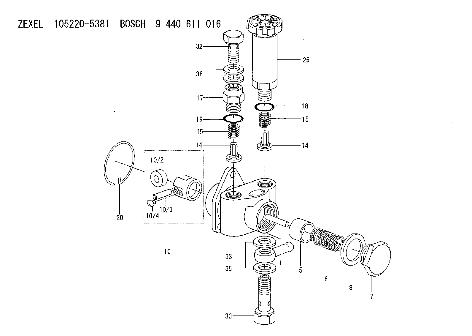
| 1. | [1] | 152003-1320 | PUMP HOUSING |
| 5. | [1] | 152100-1120 | PUMP PLUNGER |
| 6. | [1] | 152102-0400 | COMPRESSION SPRING |
| 7. | [1] | 152105-1500 | CAPSULE |
| 8. | [1] | 029332-6030 | GASKET |
| 10. | [1] | 152111-2820 | TAPPET |
| 10/2. | [1] | 152112-0100 | ROLLER |
| 10/3. | [1] | 152113-0700 | BEARING PIN |
| 10/4. | [2] | 152114-0400 | SLIDER |
| 14. | [2] | 152115-0200 | VALVE BODY |
| 14. | [2] | 152115-0200 | VALVE BODY |
| 15. | [2] | 152116-0200 | COILED SPRING |
| 15. | [2] | 152116-0200 | COILED SPRING |
| 17. | [1] | 152118-0900 | ADAPTOR |
| 18. | [1] | 029631-6060 | O-RING |
| 19. | [1] | 029631-6060 | O-RING |
| 20. | [1] | 152121-0200 | LOCKING WASHER |
| 25. | [1] | 152200-6721 | HAND PRIMER |
| 30. | [1] | 152300-5920 | EYE BOLT |
| 32. | [1] | 029731-4680 | EYE BOLT |
| 33. | [1] | 139814-0600 | INLET UNION |
| 35. | [2] | 029341-4130 | GASKET D20&13.8T2* |
| 36. | [2] | 029341-4130 | GASKET D20&13.8T2* |
Include in #1:
101692-9270
as SUPPLY PUMP
Cross reference number
Zexel num
Bosch num
Firm num
Name
Information:
Ejector Guide Rollers
(631 & 637)
Adjust
1. The ejector should operate freely without binding. To adjust the guide rollers, loosen the roller shaft clamping bolt. 2. Turn the roller (eccentric) shaft to position the roller. 3. Tighten the clamping bolt. Clearance between the guide rollers and the scraper bowl should be 3.00 to 20.00 mm (.118 to .787 in).Ejector Carrier Rollers
(631 & 637)
Adjust
1. The ejector should operate freely without dragging. To adjust the carrier rollers, loosen the clamping bolt. 2. Turn the roller (eccentric) shaft to position the roller.3. Tighten the clamping bolt. Clearance between the bottom of the ejector and the bottom of the bowl should be 1.0 to 13.0 mm (.04 to .50 in).Ejector Support Rollers
(631 & 637)
Adjust
1. The ejector should operate freely without dragging. To adjust the carrier rollers, loosen the clamping bolt. 2. Turn the roller (eccentric) shaft to position the roller. 3. Tighten the clamping bolt. The distance between rollers, outside to outside, should be .00 to 6.00 mm (.00 to .236 in) less than the narrowest dimension between the roller guide tracks.Refer to the Service Manual for your machine or contact your Caterpillar dealer for the correct adjustment procedure.Ejector Carriage Rollers
(639)
Adjust
Do not get under the push frame unless the front engine is stopped and the ejector floor is blocked.
1. Install pin in the position that will block movement of the carriage.See "Blocking the Ejector Floor Closed" in the "Safety" section of the Operation (Operator's) Guide. 2. The carriage should operate freely without binding. To adjust the carriage rollers, loosen the roller shaft clamping bolt. 3. Turn the roller (eccentric) shaft to position the rollers. 4. Tighten the clamping bolt. The distance between rollers, outside to outside, should be .00 to 1.50 mm (.00 to .060 in) less than the narrowest dimension between the guide tracks on the push frame.
(631 & 637)
Adjust
1. The ejector should operate freely without binding. To adjust the guide rollers, loosen the roller shaft clamping bolt. 2. Turn the roller (eccentric) shaft to position the roller. 3. Tighten the clamping bolt. Clearance between the guide rollers and the scraper bowl should be 3.00 to 20.00 mm (.118 to .787 in).Ejector Carrier Rollers
(631 & 637)
Adjust
1. The ejector should operate freely without dragging. To adjust the carrier rollers, loosen the clamping bolt. 2. Turn the roller (eccentric) shaft to position the roller.3. Tighten the clamping bolt. Clearance between the bottom of the ejector and the bottom of the bowl should be 1.0 to 13.0 mm (.04 to .50 in).Ejector Support Rollers
(631 & 637)
Adjust
1. The ejector should operate freely without dragging. To adjust the carrier rollers, loosen the clamping bolt. 2. Turn the roller (eccentric) shaft to position the roller. 3. Tighten the clamping bolt. The distance between rollers, outside to outside, should be .00 to 6.00 mm (.00 to .236 in) less than the narrowest dimension between the roller guide tracks.Refer to the Service Manual for your machine or contact your Caterpillar dealer for the correct adjustment procedure.Ejector Carriage Rollers
(639)
Adjust
Do not get under the push frame unless the front engine is stopped and the ejector floor is blocked.
1. Install pin in the position that will block movement of the carriage.See "Blocking the Ejector Floor Closed" in the "Safety" section of the Operation (Operator's) Guide. 2. The carriage should operate freely without binding. To adjust the carriage rollers, loosen the roller shaft clamping bolt. 3. Turn the roller (eccentric) shaft to position the rollers. 4. Tighten the clamping bolt. The distance between rollers, outside to outside, should be .00 to 1.50 mm (.00 to .060 in) less than the narrowest dimension between the guide tracks on the push frame.