Information supply pump
BOSCH
9 440 610 083
9440610083
ZEXEL
105220-5180
1052205180
MITSUBISHI
ME019635
me019635
Rating:
Scheme ###:
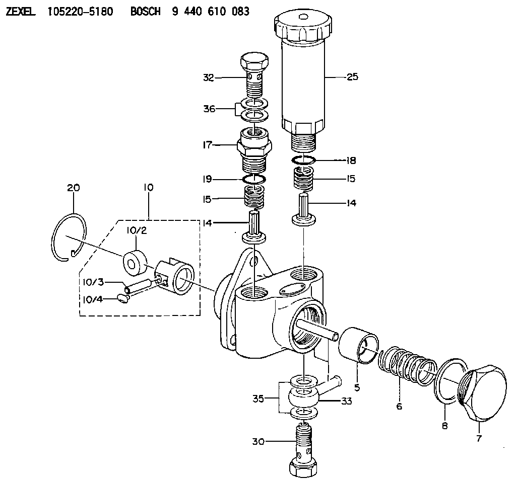
| 1. | [1] | 152003-1020 | PUMP HOUSING |
| 5. | [1] | 152100-1120 | PUMP PLUNGER |
| 6. | [1] | 152102-0400 | COMPRESSION SPRING |
| 7. | [1] | 152105-1500 | CAPSULE |
| 8. | [1] | 029332-6030 | GASKET |
| 10. | [1] | 152111-2820 | TAPPET |
| 10/2. | [1] | 152112-0100 | ROLLER |
| 10/3. | [1] | 152113-0700 | BEARING PIN |
| 10/4. | [2] | 152114-0400 | SLIDER |
| 14. | [2] | 152115-0200 | VALVE BODY |
| 14. | [2] | 152115-0200 | VALVE BODY |
| 15. | [2] | 152116-0200 | COILED SPRING |
| 15. | [2] | 152116-0200 | COILED SPRING |
| 17. | [1] | 152118-0900 | ADAPTOR |
| 18. | [1] | 029631-6060 | O-RING |
| 19. | [1] | 029631-6060 | O-RING |
| 20. | [1] | 152121-0200 | LOCKING WASHER |
| 25. | [1] | 152200-5420 | HAND PRIMER |
| 30. | [1] | 152300-7120 | EYE BOLT |
| 32. | [1] | 029731-4570 | EYE BOLT |
| 33. | [1] | 139814-0600 | INLET UNION |
| 35. | [2] | 029341-4130 | GASKET D20&13.8T2* |
| 36. | [2] | 029341-4130 | GASKET D20&13.8T2* |
Include in #1:
101401-1541
as SUPPLY PUMP
Cross reference number
Zexel num
Bosch num
Firm num
Name
Information:
Start By:a. remove valve covers
Do not let the tops of the fuel nozzles turn when the fuel lines are loosened. The nozzles will be damaged if the top of the nozzles turns in the body.
1. Loosen the fuel injection line nut at the nozzle end with tool (A) and a 7/8 5P0328 ( in) Crow Foot Wrench.2. Loosen the fuel line nut at the fuel injection line adapter with Tool (B). Remove inner fuel injection lines (1). Install caps and plugs on all fuel line openings to keep dirt out of the fuel system.
Typical Example If necessary, use Tool (D) to turn the engine so the valves do not make contact with the pistons when the valves are opened with Tool (C) to remove the push rods.3. Put compression on the valve springs with Tool (C), and remove push rods (2). Put identification marks on the push rods as to their location in the engine.4. Push the push rod end of the rocker arms down. 5. Remove the intake valve lifter with Tool (E) as follows:a. Install 5P2685 Nut (3) and 5P6601 Collet (4) on 5P2408 Outer Handle Assembly (5).b. Install 5P6599 Inner Handle Assembly (6) in 5P2408 Outer Handle Assembly (5).
Typical Examplec. Install Tool (E) in the intake valve lifter. Hold the 5P2408 Outer Handle Assembly and tighten the 5P6599 Inner Handle Assembly until the 5P6601 Collet is tight against the inside of the intake valve lifter.
Typical Exampled. Remove intake valve lifters (7) from the cylinder block with Tool (E). Put identification marks on the lifters as to their location in the engine.
Typical Example6. Remove the exhaust valve lifters with Tool (E) as follows:a. Install 5P2685 Nut (3) and 5P6601 Collet (4) on 5P2408 Outer Handle Assembly (5). The opening in the cylinder head assembly for the intake valve lifter is larger than the opening in the exhaust valve lifter side. The tooling and each valve lifter must be installed and removed from the intake valve lifter side.b. Install the outer handle assembly in the intake valve lifter side of the cylinder head assembly. Slide the flat area of 5P2408 Outer Handle Assembly (5) through the head casting and install the 5P6601 Collet in the exhaust valve lifters.
Typical Examplec. Install 5P6599 Inner Handle Assembly (6) in 5P2408 Outer Handle Assembly (5). Hold the 5P2408 Handle Assembly and tighten the 5P6599 Handle Assembly until the 5P6601 Collet is tight against the inside of the exhaust valve lifter.d. Pull the exhaust valve lifter up until the spring on the exhaust valve lifter is free from the cylinder block.e. Remove the 5P6599 Inner Handle Assembly. Slide the 5P2408 Outer Handle Assembly through the head casting and remove it from the intake valve lifter side of the cylinder head.
Typical Examplef. Use a magnet and remove exhaust valve lifters (8) from the intake valve lifter side of the cylinder head assembly. Put identification makes on the lifters as to their location in the engine.7. Remove the guide springs from the lifters.Install Valve