Information supply pump
BOSCH
9 440 610 744
9440610744
ZEXEL
105220-4891
1052204891
Rating:
Scheme ###:
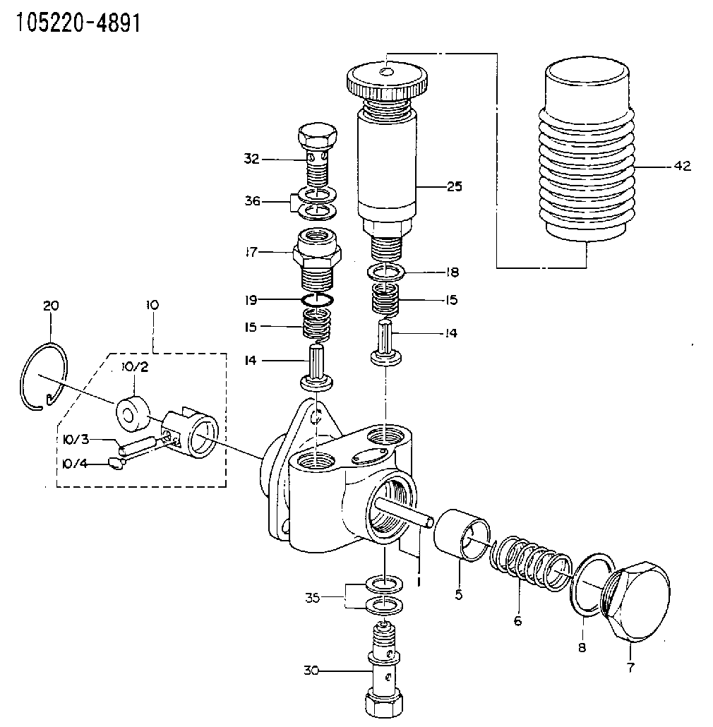
| 1. | [1] | 152000-8120 | PUMP HOUSING |
| 5. | [1] | 152100-1120 | PUMP PLUNGER |
| 6. | [1] | 152102-0400 | COMPRESSION SPRING |
| 7. | [1] | 152105-1500 | CAPSULE |
| 8. | [1] | 029332-6030 | GASKET |
| 10. | [1] | 152111-2820 | TAPPET |
| 10/2. | [1] | 152112-0100 | ROLLER |
| 10/3. | [1] | 152113-0700 | BEARING PIN |
| 10/4. | [2] | 152114-0400 | SLIDER |
| 14. | [2] | 152115-0200 | VALVE BODY |
| 14. | [2] | 152115-0200 | VALVE BODY |
| 15. | [2] | 152116-0200 | COILED SPRING |
| 15. | [2] | 152116-0200 | COILED SPRING |
| 17. | [1] | 152118-0900 | ADAPTOR |
| 18. | [1] | 029331-6030 | GASKET |
| 19. | [1] | 029631-6060 | O-RING |
| 20. | [1] | 152121-0200 | LOCKING WASHER |
| 25. | [1] | 152200-5620 | HAND PRIMER |
| 30. | [1] | 152300-0120 | EYE BOLT |
| 32. | [1] | 029731-4570 | EYE BOLT |
| 35. | [3] | 026514-1840 | GASKET D17.9&14.2T1 |
| 36. | [2] | 026514-1840 | GASKET D17.9&14.2T1 |
Cross reference number
Zexel num
Bosch num
Firm num
Name
105220-4891
9 440 610 744
SUPPLY PUMP
* K
* K
Information:
Start By:a. remove fuel injection nozzlesb. remove cylinder head assembly and spacer plate 1. Put compression on valve spring (2) with Tool (A). Remove locks (1).2. Remove Tool (A), rotocoil, spring, valve stem oil shield and valve. Put identification marks on valves with respect to their location in the cylinder head. 3. Check the spring force with Tool (B). The spring force is 257 25 N (57.8 5.6 lb). The length of spring under test force is 44.86 mm (1.766 in). The free length after test is 52.07 mm (2.050 in).4. Do Steps 1 through 3 again for the remainder of the valves.Install Valves
1. Put clean engine oil on the valve stems. Install valve (3), oil shield (4), spring (2) and rotocoil (1) in the cylinder head. 2. Put Tool (A) in position on the valve spring. Install the locks with Tool (B).
Locks can be thrown from valve when the compressor is released if they are not in their correct position on valve stem. Personal injury can be the result if not carefully removed.
3. Remove Tool (A), and hit the top of valve with a plastic hammer to be sure the locks are in their correct position on valve.4. Do Steps 1 through 3 again for the remainder of the valves.End By:a. install cylinder head assembly and spacer plateb. install fuel injection nozzles
Have questions with 105220-4891?
Group cross 105220-4891 ZEXEL
Isuzu
Nissan-Diesel
Nissan-Diesel
Nissan
Nissan-Diesel
Nissan
Nissan-Diesel
Isuzu
Isuzu
105220-4891
9 440 610 744
SUPPLY PUMP