Information supply pump
BOSCH
9 440 610 040
9440610040
ZEXEL
105220-4860
1052204860
NISSAN
16640L6000
16640l6000
Rating:
Compare Prices: .
As an associate, we earn commssions on qualifying purchases through the links below

Hacus - Forklift FPE290876 Feed Pump S4S S6S Hacus Aftermarket - New
Hacus HIGH-QUALITY CONSTRUCTION: Made with premium materials; built to withstand the demands of industrial environments; offering excellent resistance to wear; corrosion; and mechanical stress. || VERSATILE COMPATIBILITY: Engineered to fit a wide range of forklift models; making it a versatile choice for various equipment configurations. || SAFETY FIRST - FPE products are ready for use with all certifications. || LEADING THE INDUSTRY - FPE is a leader in forklift products and accessories. We take pride in making the highest quality, premium, reliable forklifts on the market. || All products tested for durability, reliability, and performance.
Hacus HIGH-QUALITY CONSTRUCTION: Made with premium materials; built to withstand the demands of industrial environments; offering excellent resistance to wear; corrosion; and mechanical stress. || VERSATILE COMPATIBILITY: Engineered to fit a wide range of forklift models; making it a versatile choice for various equipment configurations. || SAFETY FIRST - FPE products are ready for use with all certifications. || LEADING THE INDUSTRY - FPE is a leader in forklift products and accessories. We take pride in making the highest quality, premium, reliable forklifts on the market. || All products tested for durability, reliability, and performance.

£154.45
23 Mar 2018
Bosch: Bosch
Bosch 9440610040 Supply Pump
Scheme ###:
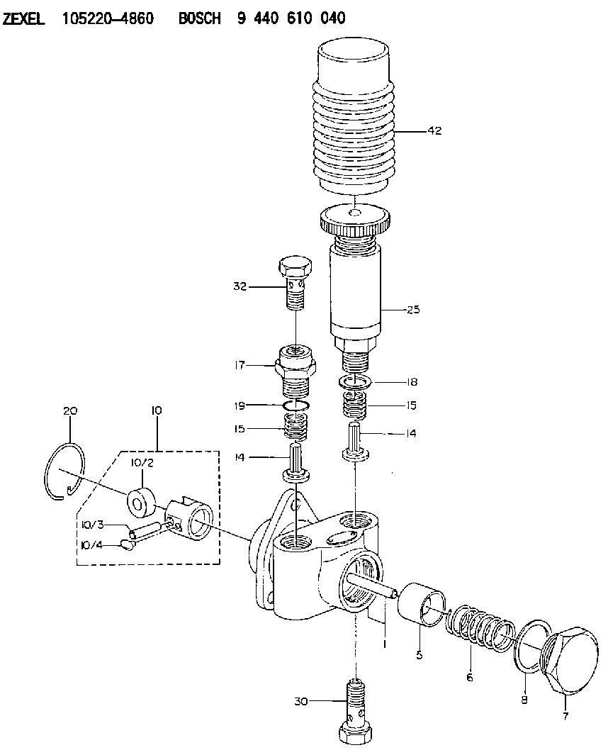
| 1. | [1] | 152000-8120 | PUMP HOUSING |
| 5. | [1] | 152100-1120 | PUMP PLUNGER |
| 6. | [1] | 152102-0400 | COMPRESSION SPRING |
| 7. | [1] | 152105-1500 | CAPSULE |
| 8. | [1] | 029332-6030 | GASKET |
| 10. | [1] | 152111-2820 | TAPPET |
| 10/2. | [1] | 152112-0100 | ROLLER |
| 10/3. | [1] | 152113-0700 | BEARING PIN |
| 10/4. | [2] | 152114-0400 | SLIDER |
| 14. | [2] | 152115-0200 | VALVE BODY |
| 14. | [2] | 152115-0200 | VALVE BODY |
| 15. | [2] | 152116-0200 | COILED SPRING |
| 15. | [2] | 152116-0200 | COILED SPRING |
| 17. | [1] | 152118-1100 | ADAPTOR |
| 18. | [1] | 029331-6030 | GASKET |
| 19. | [1] | 029631-6060 | O-RING |
| 20. | [1] | 152121-0200 | LOCKING WASHER |
| 25. | [1] | 152200-5620 | HAND PRIMER |
| 30. | [1] | 152300-5520 | EYE BOLT |
| 32. | [1] | 029731-4080 | EYE BOLT |
Include in #1:
101641-9030
as SUPPLY PUMP
Cross reference number
Zexel num
Bosch num
Firm num
Name
Information:
Start By:a. disassemble governorb. remove fuel injection pumps 1. Remove cover (1) from the fuel injection pump housing. 2. Remove rack (2) from the fuel injection pump housing.
If the original lifters are to be installed in the fuel injection pump housing, put identification marks on them as to their location in the housing.
3. Remove lifters (3) from the fuel injection pump housing. 4. Put the fuel injection pump housing on end on blocks, and use Tool (A) to remove snap ring (4) from the camshaft. 5. Use a soft hammer to push the camshaft toward the governor end of the fuel injection pump housing to loosen washer (5) on the camshaft. Remove washer (5). 6. Remove camshaft (6) from the fuel injection pump housing. 7. Remove bearings (7) from the drive end of the fuel injection pump housing. 8. Remove bearings (8) from the governor end of the fuel injection pump housing.Assemble Fuel Injection Pump Housing
Be sure all oil passages are clear and put clean engine oil on all parts before assembly.1. Use Tool (A) to install bearing (2) in the governor end of the fuel injection pump housing with joint (3) toward the top of the fuel injection pump housing. Install the bearing so it is 0.25 0.20 mm (.010 0.008 in) below the surface of the housing.2. Use Tool (A) to install bearing (1) in the governor end of the fuel injection pump housing so it is 7.16 0.13 mm (0.282 0.005 in) below the surface of the housing. 3. Use Tool (A) to install bearing (4) in the drive end of the fuel injection pump housing with the joint in the bearing toward the top of the fuel injection pump housing. Install the bearing so it is 1.00 0.25 mm (0.039 0.010 in) below the surface of the housing. 4. Install plate assembly (6) of Tool (C) on the drive end of the fuel injection pump housing to install the bearing for the rack. Use clean grease to hold the new rack bearing on driver (5) of Tool (C). Install the driver and bearing in plate assembly (6) with the groove in the driver in alignment with the pin in the plate. Use a hammer to push the bearing into position. The bearing will be installed to the correct depth when the shoulder of the driver is against plate assembly (6).5. Remove Tool (C) from the fuel injection pump housing. The rack bearing must be installed so it is 0.25 0.25 mm (0.010 0.010 in) below the surface of the housing. 6. Install camshaft (7) in the fuel injection pump housing.7. Put the fuel injection pump housing on end, and put a block under the camshaft. 8. Put washer (9) over the end of the camshaft, and use Tool (A) and a spacer (8) that has an inside diameter of 38.1 mm (1.5 in) and a length of 31.75 mm (1.25 in) to push the washer