Information supply pump
BOSCH
9 440 610 001
9440610001
ZEXEL
105220-4620
1052204620
NISSAN
16640J2202
16640j2202
Rating:
Compare Prices: .
As an associate, we earn commssions on qualifying purchases through the links below

$194.47
21 Nov 2024
2.1[0.95] pounds
Amazon.com
Hacus - Forklift FPE318042 FEED PUMP S4S S6S Hacus Aftermarket - New
Hacus HIGH-QUALITY CONSTRUCTION: Made with premium materials; built to withstand the demands of industrial environments; offering excellent resistance to wear; corrosion; and mechanical stress. || VERSATILE COMPATIBILITY: Engineered to fit a wide range of forklift models; making it a versatile choice for various equipment configurations. || SAFETY FIRST - FPE products are ready for use with all certifications. || LEADING THE INDUSTRY - FPE is a leader in forklift products and accessories. We take pride in making the highest quality, premium, reliable forklifts on the market. || All products tested for durability, reliability, and performance.
Hacus HIGH-QUALITY CONSTRUCTION: Made with premium materials; built to withstand the demands of industrial environments; offering excellent resistance to wear; corrosion; and mechanical stress. || VERSATILE COMPATIBILITY: Engineered to fit a wide range of forklift models; making it a versatile choice for various equipment configurations. || SAFETY FIRST - FPE products are ready for use with all certifications. || LEADING THE INDUSTRY - FPE is a leader in forklift products and accessories. We take pride in making the highest quality, premium, reliable forklifts on the market. || All products tested for durability, reliability, and performance.
Scheme ###:
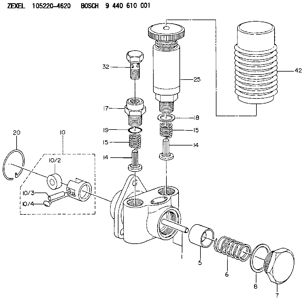
| 1. | [1] | 152000-8120 | PUMP HOUSING |
| 5. | [1] | 152100-1120 | PUMP PLUNGER |
| 6. | [1] | 152102-0600 | COMPRESSION SPRING |
| 7. | [1] | 152105-1500 | CAPSULE |
| 8. | [1] | 029332-6030 | GASKET |
| 10. | [1] | 152111-2820 | TAPPET |
| 10/2. | [1] | 152112-0100 | ROLLER |
| 10/3. | [1] | 152113-0700 | BEARING PIN |
| 10/4. | [2] | 152114-0400 | SLIDER |
| 14. | [2] | 152115-0200 | VALVE BODY |
| 14. | [2] | 152115-0200 | VALVE BODY |
| 15. | [2] | 152116-0200 | COILED SPRING |
| 15. | [2] | 152116-0200 | COILED SPRING |
| 17. | [1] | 152118-0900 | ADAPTOR |
| 18. | [1] | 029331-6030 | GASKET |
| 19. | [1] | 029631-6060 | O-RING |
| 20. | [1] | 152121-0200 | LOCKING WASHER |
| 25. | [1] | 152200-5620 | HAND PRIMER |
| 32. | [1] | 029731-4080 | EYE BOLT |
Include in #1:
101431-9710
as SUPPLY PUMP
Cross reference number
Zexel num
Bosch num
Firm num
Name
Information:
Action Required
See the attached procedure.
Service Claim Allowances
Group 1 Affected Product
All Group 2 Affected Product
This is a 1-hour job.
All Group 3 Affected Product
This is a .3-hour job. Submit a supplemental claim for Group 3 if a claim for Group 1 or 2 has already been submitted.
Parts Disposition
Handle the parts in accordance with your Warranty Bulletin on warranty parts handling.
Attach. (1-Rework Procedure)Rework Procedure
Refer to the following instructions and illustrations. Replace the existing fuel lines and their related parts with the new fuel line groups.
To insure correct clamp locations, install left and right fuel line groups as assembled. However, if clamps are removed, mark locations to insure correct positions when reassembling.
On the 992C Wheel Loader, it is necessary to remove the 6N8322 Air Outlet Tube Assembly to be able to install the right bank fuel line group.
Tighten the fuel line clamp screws to a torque of 2.25 N m (20 lb in). Do not over tighten. Use a 6V6069 Torque Screwdriver or similar tool to tighten the screws.
Group 1 Procedure
1. Clean and paint the new 6I0361 and 7E3539 Fuel Line Groups before proceeding to the job site.A) "Tape Off" the number 3, 5, and 6 fuel lines in the area of the tower clamp. (See Illustration 1 - Part 4 of 5, Section C-C)B) Install 5F2807 Plastic Caps and 2F2990 Plastic Plugs on the ends of the fuel lines.C) Clean and paint the fuel line groups.D) After drying completely, remove the tape. Do not remove the plastic caps and plugs until the fuel lines are ready to be installed on the engine. Transport the fuel line groups in their original boxes.2. Remove all mounting bolts from the fuel line brackets at the aftercooler housing. Except for the tower clamp assembly, new mounting bolts and washers will be used. Keep the washers. The washers may be needed later as spacers.3. A) Disassemble the tower clamp assembly behind the fuel injection pump. The 9Y3356 Clamp and 9Y3359 Clamp As. that form the tower clamp will be reused. (See Illustration 1 - Part 4 of 5, Section C-C)B) Disconnect the 2 line clamps from the 9Y3361 Bracket (Front V Bracket).C) Disconnect the 6 line clamps from the 7E5779 Bracket (Large V Bracket).4. Disconnect all the fuel lines at the fuel injection pump and at the adaptors in the valve cover bases.5. A) Remove the left and right side fuel line groups as separate assemblies.B) Remove the 9Y3361 Bracket (Front V Bracket). Replace it with a new 6I0347 Bracket.6. Remove the plastic caps and plugs from the fuel lines. Set the new 6I0361 Fuel Lines Group (left side) and the new 7E3539 Fuel Lines Group (right side) in place and hand tighten the fuel nuts. (See Illustration 1 - Part 1 of 5). If any of the ends of the individual fuel lines are not square with the bonnets in the fuel injection pump or with the adaptors in the valve cover bases, gently bend the lines by hand to align the