Information supply pump
BOSCH
9 440 610 741
9440610741
ZEXEL
105220-4271
1052204271
Rating:
Scheme ###:
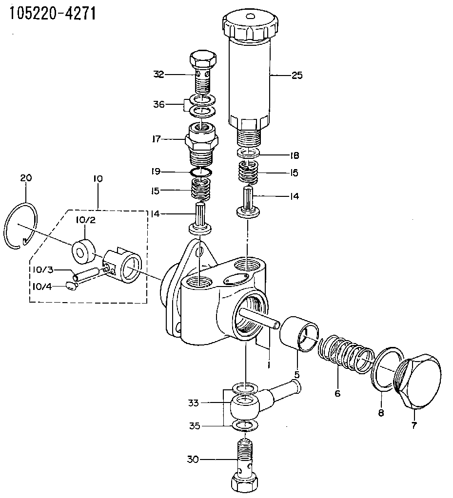
| 1. | [1] | 152000-8120 | PUMP HOUSING |
| 5. | [1] | 152100-1120 | PUMP PLUNGER |
| 6. | [1] | 152102-0600 | COMPRESSION SPRING |
| 7. | [1] | 152105-1500 | CAPSULE |
| 8. | [1] | 029332-6030 | GASKET |
| 10. | [1] | 152111-2820 | TAPPET |
| 10/2. | [1] | 152112-0100 | ROLLER |
| 10/3. | [1] | 152113-0700 | BEARING PIN |
| 10/4. | [2] | 152114-0400 | SLIDER |
| 14. | [2] | 152115-0200 | VALVE BODY |
| 14. | [2] | 152115-0200 | VALVE BODY |
| 15. | [2] | 152116-0200 | COILED SPRING |
| 15. | [2] | 152116-0200 | COILED SPRING |
| 17. | [1] | 152118-0900 | ADAPTOR |
| 18. | [1] | 029331-6030 | GASKET |
| 19. | [1] | 029631-6060 | O-RING |
| 20. | [1] | 152121-0200 | LOCKING WASHER |
| 25. | [1] | 152200-5620 | HAND PRIMER |
| 30. | [1] | 152300-0920 | EYE BOLT |
| 32. | [1] | 029731-4080 | EYE BOLT |
| 33. | [1] | 029711-4310 | INLET UNION |
| 35. | [2] | 029341-4130 | GASKET D20&13.8T2* |
| 36. | [2] | 029341-4130 | GASKET D20&13.8T2* |
Cross reference number
Zexel num
Bosch num
Firm num
Name
Information:
Turbocharger
Turbocharger
(1) Turbine wheel. (2) Compressor wheel. (3) Exhaust outlet. (4) Air inlet. (8) Oil inlet passage. (9) Oil outlet. (10) Exhaust inlet.The turbocharger is installed on the exhaust manifold. All the exhaust gases from the engine go through the turbocharger.The exhaust gases enter exhaust inlet (10) and go through the blades of turbine wheel (1), causing the turbine wheel and compressor wheel (2) to turn.When the compressor wheel turns, it pulls filtered air from the air cleaner through air inlet (4). The air is put in compression by action of the compressor wheel and is pushed to the inlet manifold of the engine.When engine load increases, more fuel is injected into the engine cylinders. The volume of exhaust gas increases, which causes the turbocharger turbine wheel and compressor wheel to turn faster. The increased rpm of the compressor wheel increases the quantity of inlet air. As the turbocharger provides additional inlet air, more fuel can be burned. This results in more horsepower from the engine at higher altitudes.Maximum rpm of the turbocharger is controlled by the high idle speed setting and the height above sea level at which the engine is operated.The bearings for the turbocharger use engine oil for lubrication. The oil comes in through oil inlet (8) and goes through passages in the center section for lubrication of the bearings. Oil from the turbocharger goes out through oil outlet (9) in the bottom of the center section and goes back to the engine oil pan.The turbocharger allows the engine to run properly at high altitudes where the air is leaner. In this application, the turbocharger does not give more power. It compensates for leaner air.Crankcase Ventilation System
The air intake system is also equipped with a crankcase ventilation system, or breather. The piston intake stroke pulls in atmospheric air to the crankcase area.
Crankcase Ventilation
(1) Ventilation hose. (2) Breather.The fumes in the crankcase flow through a passage of the engine block to the valve cover, through hose (1) and breather (2) to the atmosphere.Electrical System
The electrical system is a 12 volt, negative ground system that has two basic circuits. They are the starting circuit and the charging circuit, which includes the low amperage circuit with warning lights and gauges. Some of the electrical components are used in more than one circuit.The starting circuit is in operation only when the key start switch is turned to the START position. In the starting circuit, the transmission neutral/switch must be closed before the starter solenoid is energized (electrical energy).The charging circuit is in operation when the engine is running. The alternator in the charging circuit gives current to the electrical system. The battery keeps the storage of the current. A voltage regulator in the circuit, on the alternator housing, controls the amount of current output to the battery. The voltmeter in the circuit shows system voltage.Reference: For a complete electrical schematic, see Schematics For Backhoe Loader Electrical System, Form No. SENR3165; Backhoe Loader Electrical System (With Roading Arrangement), Form No. SENR3924;