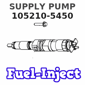
Information supply pump
BOSCH
9 440 610 179
9440610179
ZEXEL
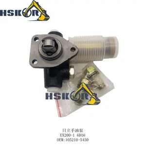
105210-5450
1052105450
MITSUBISHI
ME738673
me738673
Rating:
You can express buy:
USD 279.99
14-06-2025
14-06-2025
for hitachi Hand Oil Pump EX200-1 6D16 Excavator Engine Parts Fuel Supply Pump 105210-5450
Scheme ###:
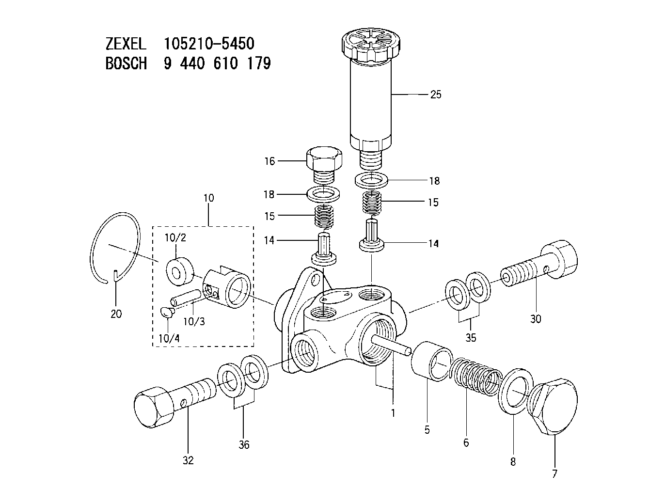
| 1. | [1] | 152004-0920 | PUMP HOUSING |
| 5. | [1] | 152100-1120 | PUMP PLUNGER |
| 6. | [1] | 152102-0400 | COMPRESSION SPRING |
| 7. | [1] | 152105-1500 | CAPSULE |
| 8. | [1] | 029332-6030 | GASKET |
| 10. | [1] | 152111-2920 | TAPPET |
| 10/2. | [1] | 152112-1000 | ROLLER |
| 10/3. | [1] | 152113-0100 | BEARING PIN |
| 10/4. | [2] | 152114-0700 | SLIDER |
| 14. | [2] | 152115-0200 | VALVE BODY |
| 14. | [2] | 152115-0200 | VALVE BODY |
| 15. | [2] | 152116-0200 | COILED SPRING |
| 15. | [2] | 152116-0200 | COILED SPRING |
| 16. | [1] | 152117-0100 | CAPSULE |
| 18. | [2] | 029331-6030 | GASKET |
| 18. | [2] | 029331-6030 | GASKET |
| 20. | [1] | 152121-0200 | LOCKING WASHER |
| 25. | [1] | 152200-5620 | HAND PRIMER |
| 30. | [1] | 152300-6920 | EYE BOLT |
| 32. | [1] | 139814-0900 | EYE BOLT |
| 35. | [2] | 029341-4130 | GASKET D20&13.8T2* |
| 36. | [2] | 029341-4130 | GASKET D20&13.8T2* |
Include in #1:
101602-1390
as SUPPLY PUMP
Cross reference number
Zexel num
Bosch num
Firm num
Name
Information:
The front plate is bolted inside the timing gear case. Do not attempt to remove this plate along with the timing gear case by tapping.
Front plate attaching bolts8. Timing gear backlash measurement Measure the backlash of each gear and keep a record of it for correct installation. Replace the gears if the backlash exceeds the limit.
Unit: mm (in.)
Measuring timing gear backlash9. Idler gear removal To remove the idler gear, rotate the gear in a direction of the helix of the teeth to pull it out of mesh.
Removing idler gear10. Camshaft removal (1) Remove the bolts that hold the thrust plate. (2) Pull the camshaft out of the cylinder block.
Do not cause damage to the lobes or bearing journals when removing the camshaft.
Removing camshaft11. Fuel injection pump camshaft removal(1) Remove the stopper bolt.
Removing camshaft stopper bolt(2) Tap the rear end of the camshaft with a copper bar to push it out of the front side of the cylinder block.
Removing fuel injection pump camshaft12. Gear removal (when required) To remove the gears from the camshaft and fuel injection pump camshaft, use an arbor press.13. Oil pump removal Remove the bolts that hold the oil pump to the cylinder block and remove the pump.
Removing oil pump14. Front plate removal Remove four bolts that hold the front plate in position. Tap the plate lightly with a plastic hammer to separate the gasket.
Removing front plateCYLINDER BLOCK, CRANKSHAFT, PISTONS AND OIL PAN
1 Oil pan2 Oil screen3 Connecting rod cap4 Connecting rod bearing (lower half) (Remove 5 thru 10 as an assembly.)5 Connecting rod6 Piston pin7 No. 1 ring8 No. 2 ring9 Oil ring10 Piston11 Connecting rod bearing (upper half)12 Main bearing cap13 Main bearing (lower half)14 Crankshaft15 Main bearing (upper half)16 Cylinder block When the cylinder block is to be discarded, remove the components (pressure relief valve, etc.) from the block for reuse. 1. Oil pan removal (1) Turn the engine upside down.(2) Tap the bottom corners of the oil pan with a plastic hammer to remove the oil pan.
Do not attempt to pry off the oil pan by inserting a screwdriver or a chisel between the oil pan and cylinder block. Damage to the oil pan can be the result.
Removing oil pan2. Oil screen removal Loosen the nut that holds the oil screen in position and remove the screen.
Removing oil screen3. Thrust clearance measurement for connecting rod big endInstall the connecting rod to its crankpin and tighten the cap nuts to the specified torque. Measure the thrust clearance with a feeler gauge. If the clearance exceeds the limit, replace the connecting rod.
Measuring thrust clearance for connecting rod big end
Unit: mm (in.)4. Connecting rod cap removal (1) Lay the cylinder block on its side.(2) Put identification on each connecting rod and cap combination as to its location in the engine.(3) Remove the caps.
Removing connecting rod caps5. Piston removal (1) Turn the crankshaft until the piston is at top center. (2) Push the piston and connecting rod away from the crankshaft with the handle of