Information strap
BOSCH
9 421 621 392
9421621392
ZEXEL
153405-0120
1534050120
ISUZU
9813252650
9813252650

Rating:
Include in ###:
Cross reference number
Zexel num
Bosch num
Firm num
Name
153405-0120
9 421 621 392
9813252650 ISUZU
STRAP
C 14GJ LINK GOV
C 14GJ LINK GOV
153405-0120
9 421 621 392
6053131960 HINO
STRAP
C 14GJ LINK GOV
C 14GJ LINK GOV
153405-0120
9 421 621 392
223171110A HINO
STRAP
A C 14GJ LINK GOV
A C 14GJ LINK GOV
Information:
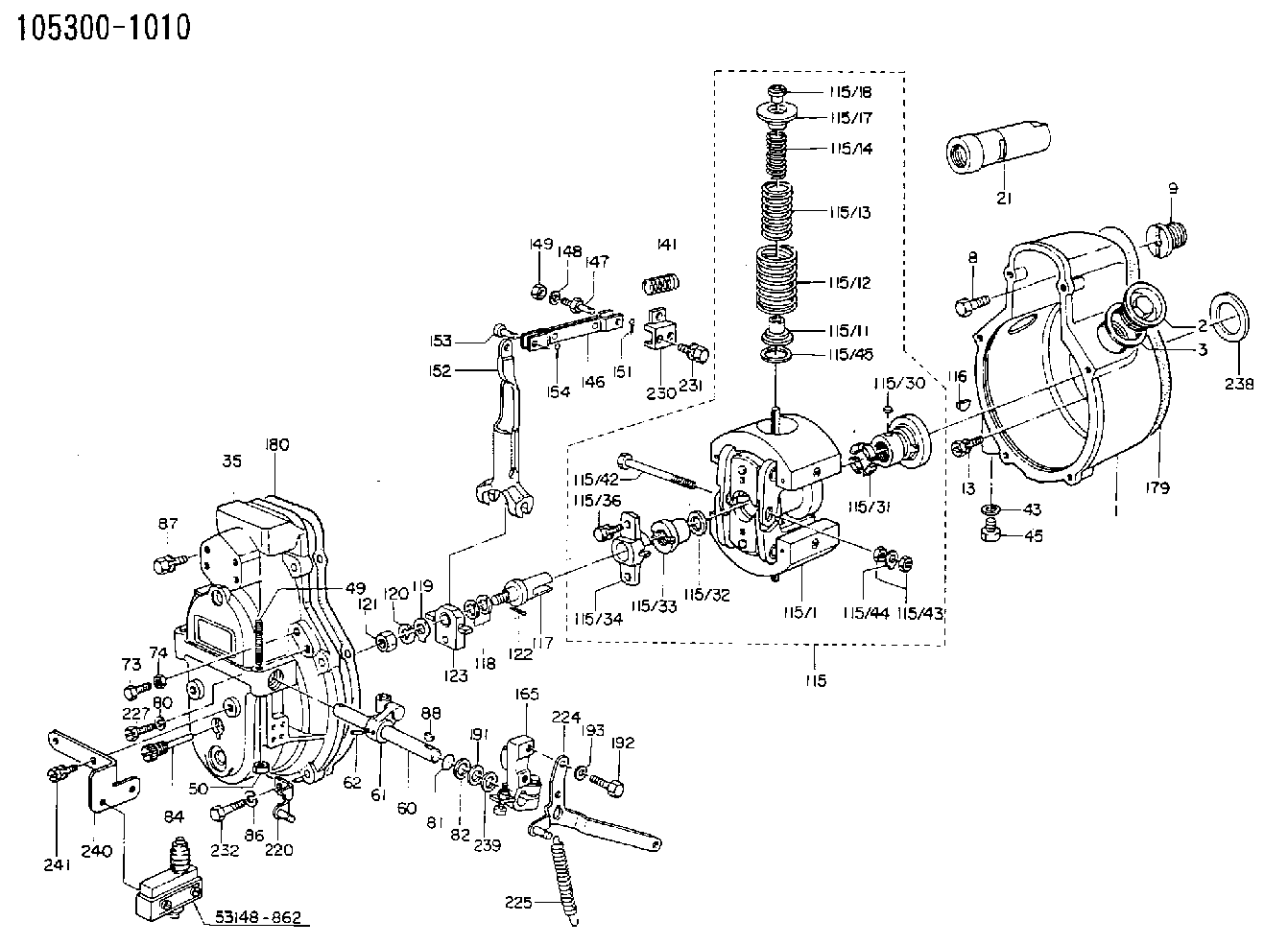
start by:a) remove fuel ratio controlb) remove shut off solenoid 1. Put a mark of identification on the shaft and lever (1) for correct location at assembly. Loosen the bolt and remove lever (1) from the shaft. 2. Remove the bolts, cover (3) and the gasket.3. Remove the bolt, high idle housing (2) and the gasket. 4. Remove the bolt and housing (4) from the governor. 5. Remove bolt (6) from the stop collar.6. Remove stop collar (5) and the spring from the shaft. 7. Remove the plug from the fuel injection pump housing and install tool (A) with square end (flat end) down. Move the governor control to the "FUEL ON" position until the right rack stops against the timing pin. The racks are now in the center (zero) position. 8. Remove bolts (8) that hold the governor housing to the fuel injection pump housing.9. Remove governor housing (7). 10. Disconnect lines (10) and (11) at the governor control plate.11. Remove the bolts, governor control plate (9) and gasket.
Cover the fuel injection pump housing to keep dirt and all foreign material out of the pump housing.
The drive assembly must be removed from the governor control plate before the control plate can be installed. 12. Remove retainer ring (12) from the drive assembly. 13. Remove dowel (14) and drive assembly (13) from the governor control plate.Install Governor (Later)
Make sure there is no dirt or foreign material in the pump housing.
1. Put gasket (2) in position and install governor control plate (1) and the bolts. 2. Put governor drive (3) in position. Make an alignment of the groove (slot) in the bottom end of the governor drive with the notch in the end of the drive pinion assembly.3. Align the marks on the top of drive (3), stop (4) and the gear. 4. Install dowel (5) in the hole in the gear and stop (4). 5. Install retainer ring (6) on the gear. 6. Put the gasket and governor housing (7) in position on the plate. Install the bolts.7. Connect two lines (8) to the plate. 8. Put spring (11) and collar (9) in position on the shaft. Make an alignment of screw (10) and the groove in the shaft. Tighten screw (10).9. Check the fuel rack setting at this time. See FUEL RACK SETTING in TESTING AND ADJUSTING. 10. If nut (13) was loosened it must be tightened at this time. Tighten nut (13) to a torque of 9 3 lb.ft. (12 4 N m).11. Put the gasket and cover (12) in position. Make sure lever (14) is in position under the collar. Install the bolt that holds cover (12) to the housing. 12. Put the gasket and cover (16) in position and install the bolt.13. Install the gasket, plate (15) and the bolts. 14. Make an alignment of the mark on the shaft with mark on lever (17) and install the lever. Tighten the bolt.
If the lever and the shaft are not in correct alignment,
Have questions with 153405-0120?
Group cross 153405-0120 ZEXEL
Isuzu
153405-0120
9 421 621 392
9813252650
STRAP
Hino
153405-0120
9 421 621 392
6053131960
STRAP
153405-0120
9 421 621 392
223171110A
STRAP