Information start advance assy
BOSCH
9 421 621 225
9421621225
ZEXEL
159800-0520
1598000520
ISUZU
8972132890
8972132890
Rating:
Scheme ###:
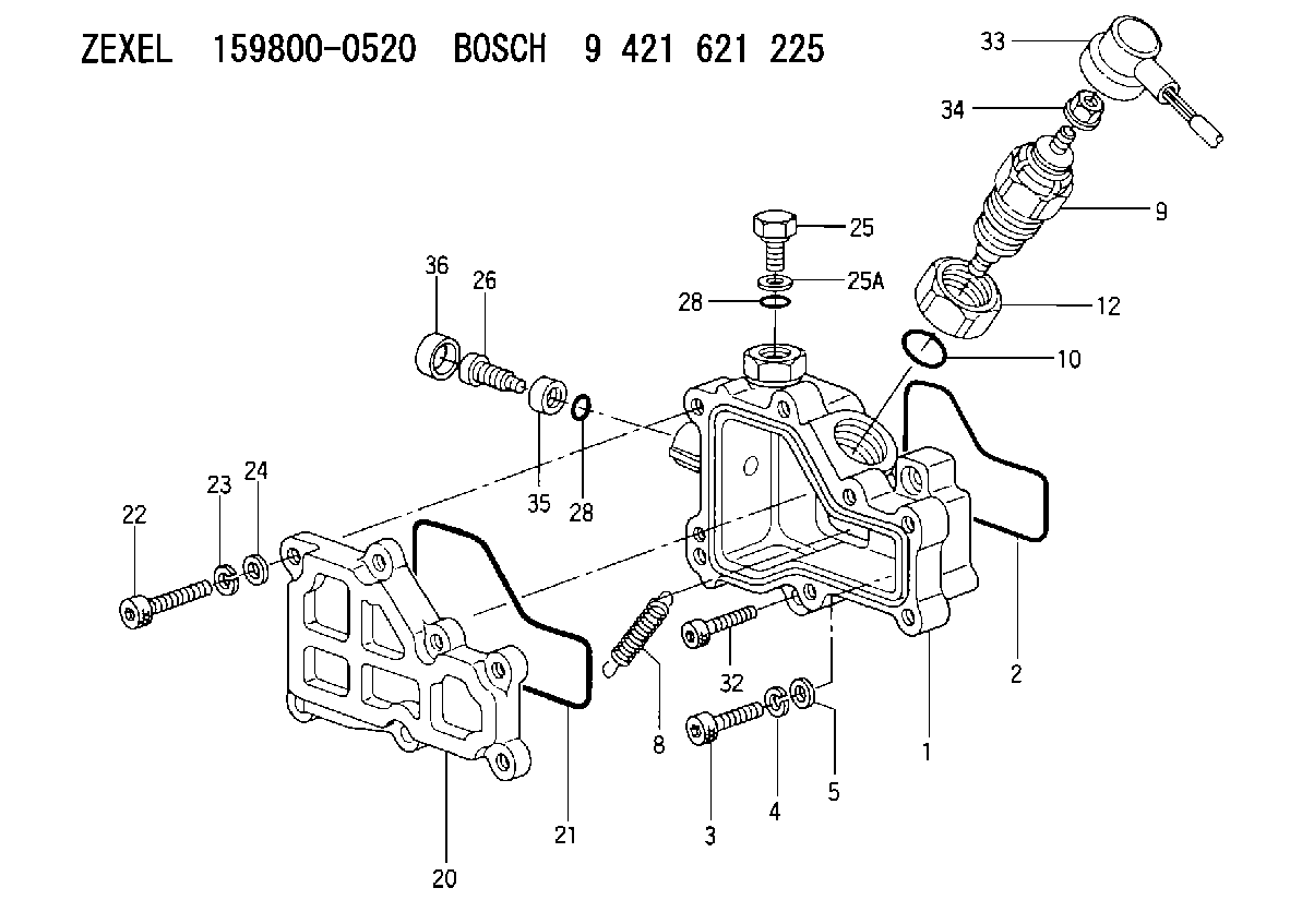
| 1. | [1] | 159820-0321 | DIAPHRAGM HOUSING |
| 2. | [1] | 159822-0200 | SEAL RING |
| 3. | [2] | 010206-2540 | HEX-SOCKET-HEAD CAP SCREW M6P1L25 |
| 4. | [4] | 029320-6010 | LOCKING WASHER |
| 5. | [4] | 139306-0400 | PLAIN WASHER |
| 8. | [1] | 159823-0200 | COILED SPRING |
| 9. | [1] | 159810-0421 | SOLENOID |
| 10. | [1] | 139717-0000 | O-RING |
| 12. | [1] | 139224-0100 | UNION NUT |
| 20. | [1] | 159821-0200 | COVER |
| 21. | [1] | 159822-0300 | SEAL RING |
| 22. | [7] | 010206-2840 | HEX-SOCKET-HEAD CAP SCREW |
| 23. | [7] | 029320-6010 | LOCKING WASHER |
| 24. | [7] | 139306-0400 | PLAIN WASHER |
| 25. | [1] | 159823-1901 | BLEEDER SCREW |
| 25A. | [1] | 026508-1140 | GASKET D11.4&8.2T1 |
| 26. | [1] | 159823-1400 | FLAT-HEAD SCREW |
| 28. | [2] | 139706-0100 | O-RING |
| 28. | [2] | 139706-0100 | O-RING |
| 32. | [2] | 010206-2840 | HEX-SOCKET-HEAD CAP SCREW |
| 33. | [1] | 159811-0800 | WIRE |
| 34. | [1] | 146621-1000 | UNION NUT |
| 35. | [1] | 159823-1500 | UNION NUT |
| 36. | [1] | 159823-2001 | CAPSULE |
Include in #1:
107492-1044
as _
Cross reference number
Zexel num
Bosch num
Firm num
Name
159800-0520
9 421 621 225
8972132890 ISUZU
START ADVANCE ASSY
K 14GH START ADVANCE ASSY GOV
K 14GH START ADVANCE ASSY GOV
159800-0520
9 421 621 225
8972158700 ISUZU
START ADVANCE ASSY
A K 14GH START ADVANCE ASSY GOV
A K 14GH START ADVANCE ASSY GOV
Information:
9. Remove bracket assembly (16) and link (17). 10. Put identification marks on fuel racks (18) and (19), and remove the fuel racks. 11. Put identification marks on each spacer (20) and lifter (21) so they can be installed in their original position. 12. Remove fuel injection pump camshaft (22) from the pump housing.13. Remove O-ring seal (23). 14. Inspect link pivot shaft (24) and bracket locating pin (25). Make a replacement by removal of shaft (24) and dowel (25) with Tool (D). 15. Inspect upper bearing (26) and the lower bearing that hold the pinion gear in the pump housing.16. Make a replacement of bearings (26) if necessary.17. Inspect idler gear shaft (27). If a replacement is necessary, remove the shaft with Tooling (D). 18. Inspect fuel rack bearings (28) and camshaft bearings (29). If a replacement is necessary, remove bearings (28) and (29).19. Use Tooling (E) to remove bearings (28). 20. Remove regulator valve (30). 21. Remove pin (31) to disassemble the regulator valve, and inspect the components.22. Piston (32) must move freely in valve body (30).23. Make a reference to the Specifications for spring (34).24. Make a replacement of O-ring seals (33).Assemble Fuel Injection Pump Housing
Pin (2) must not extend out of either side of valve body (3).
1. Install spring (4), piston (1) and pin (2) in valve body (3).2. Put clean engine oil on the valve body and O-ring seals (5). Install the oil bypass valve in the pump housing. Tighten the bypass valve body to a torque of 68 14 N m (50 10 lb ft). 3. Install the camshaft front and rear bearings with Tooling (A). Install the front bearing until it is a distance of 1.0 0.5 mm (.04 .02 in) from the front surface of the pump housing. Make sure both oil holes in bearing are in alignment with the oil holes in the pump housing. 4. Put Tool (B) in the fuel pump housing with the dowels of Tool (B) in alignment with the left fuel rack bore. Install the bolt that holds the tool in place on the housing.5. Put a new bearing in position with the tab of the bearing up. Install the bearing with Tool (C) until the shoulder of Tool (C) makes contact with Tool (B).6. Turn Tool (B), and make an alignment of the dowels on Tool (B) with the right fuel rack bore.7. Do Step 3 again for the left fuel rack bearing. 8. Install shaft (6) to a height of 16.8 0.5 mm (.66 .02 in). 9. Make sure the chamfer on the lower bearing for the pinion gear is toward the inside and the notch is in the location shown. Install the bearing 28.4 0.5 mm (1.12 .02 in) below the bearing bore surface with Tooling (D).10. Make sure the chamfer on the upper bearing for the pinion gear is toward the inside and the notch is in the location shown. Use
Have questions with 159800-0520?
Group cross 159800-0520 ZEXEL
Isuzu
159800-0520
9 421 621 225
8972132890
START ADVANCE ASSY
159800-0520
9 421 621 225
8972158700
START ADVANCE ASSY