Information spacer bushing
BOSCH
9 461 610 564
9461610564
ZEXEL
146720-0100
1467200100
ISUZU
8941227300
8941227300

Rating:
Include in ###:
Number on scheme 67/48/1

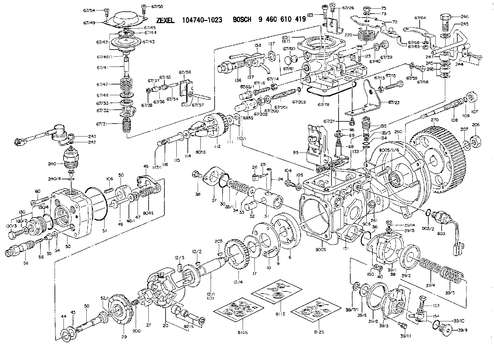
1047401023
as SPACER BUSHING
L3.9
1047401131
as SPACER BUSHING
1047401132
as SPACER BUSHING
L3.9
1047401141
as SPACER BUSHING
1047401142
as SPACER BUSHING
L3.9
1047401490
as SPACER BUSHING
1047401491
as SPACER BUSHING
L3.9
1047401710
as SPACER BUSHING
1047401720
as SPACER BUSHING
L3.9
1047402020
as SPACER BUSHING
1047402022
as SPACER BUSHING
L3.9
1047402030
as SPACER BUSHING
1047402031
as SPACER BUSHING
L3.9
Cross reference number
Zexel num
Bosch num
Firm num
Name
146720-0100
9 461 610 564
8941227300 ISUZU
SPACER BUSHING
C 11FV SPACER parts(VE) Others
C 11FV SPACER parts(VE) Others
146720-0100
9 461 610 564
1679822J01 NISSAN
SPACER BUSHING
C 11FV SPACER parts(VE) Others
C 11FV SPACER parts(VE) Others
146720-0100
9 461 610 564
164200F001 NISSAN-DIESEL
SPACER BUSHING
C 11FV SPACER parts(VE) Others
C 11FV SPACER parts(VE) Others
146720-0100
9 461 610 564
RFG113T31 MAZDA
SPACER BUSHING
C 11FV SPACER parts(VE) Others
C 11FV SPACER parts(VE) Others
Information:
Start By:a. remove valve covers Call out (1) and (2) are not used in this removal procedure. Call outs begin with number (3). 1. Remove bolts (3) that hold the valve cover bases to the cylinder head assembly. Remove valve cover bases (4).
To prevent damage to the fuel injection nozzle, hold adapter assembly (5) in position at the of injection nozzle (6) when fuel line nut (7) is loosened or tightened.
2. Use Tool (A) and a 7/8 5P0328 Crow Foot ( in) to loosen the fuel injection line nut at the nozzle end. 3. Use Tool (B) to loosen the nut at the fuel injection line adapter end. Remove inner fuel injection lines (8). Install caps and plugs on all fuel injection line openings to keep dirt out of the fuel system. 4. Remove bolts (9) that hold the rocker shaft assemblies to the cylinder head assembly.5. Remove rocker shaft assemblies (10). 6. Put identification marks on the push rods as to their location in the engine. Remove push rods (11). 7. Put identification marks on the bridges as to their location in the engine. Remove bridges (12) from the dowels on the cylinder head assembly.Install Rocker Shaft Assemblies & Push Rods
1. Put clean engine oil on the bridges and dowels. Install the original bridges in their respective locations. New bridges can be mixed.2. Install bridges (1) on the bridge dowels. While firmly pressing 0.5 to 4.5 kg (1 to 10 lb) straight down on the top contact surface of the bridge, turn the adjusting screw clockwise until contact is made with the valve stem. Turn the screw an additional 1/31/2 20 to 30 degrees ( to of 1 hex on nut). This will straighten the dowel in the guide and compensate for the slack in the threads. Hold the adjusting screw in this position and tighten the locknut to a torque of 30 4 N m (22 3 lb ft). Install the original push rods in their respective locations in the engine. New push rods can be mixed.3. Install push rods (2). 4. Put rocker shaft assemblies (3) in position on the cylinder head assembly.5. Put clean engine oil on the threads of the bolts that hold the rocker shaft assemblies in place. Tighten the bolts first to a torque of 270 25 N m (200 18 lb ft). Start with the bolt in the center of the rocker shaft assembly. Tighten the bolts again to a torque of 450 20 N m (330 15 lb ft). Tighten the bolts again by hand to a torque of 450 20 N m (330 15 lb ft).
Do not cause damage to the O-ring seals on the inner fuel lines.
6. Install inner fuel injection lines (4). Tighten the fuel injection line adapter nuts (5) to a torque 40 7 N m (30 5 lb ft) with Tool (A).
Do not let the tops of the fuel nozzles turn when the fuel
Have questions with 146720-0100?
Group cross 146720-0100 ZEXEL
Isuzu
146720-0100
9 461 610 564
8941227300
SPACER BUSHING
Nissan
146720-0100
9 461 610 564
1679822J01
SPACER BUSHING
Nissan-Diesel
146720-0100
9 461 610 564
164200F001
SPACER BUSHING
Mazda
146720-0100
9 461 610 564
RFG113T31
SPACER BUSHING