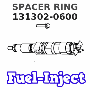
Information spacer ring
BOSCH
9 411 610 218
9411610218
ZEXEL
131302-0600
1313020600
ISUZU
9812250450
9812250450
Rating:
Include in ###:
Cross reference number
Zexel num
Bosch num
Firm num
Name
131302-0600
9 411 610 218
9812250450 ISUZU
SPACER RING
C 14FL RING parts(A,AD) Others
C 14FL RING parts(A,AD) Others
131302-0600
9 411 610 218
6053125670 HINO
SPACER RING
C 14FL RING parts(A,AD) Others
C 14FL RING parts(A,AD) Others
131302-0600
9 411 610 218
221241040A HINO
SPACER RING
A C 14FL RING parts(A,AD) Others
A C 14FL RING parts(A,AD) Others
131302-0600
9 411 610 218
ME704213 MITSUBISHI
SPACER RING
C 14FL RING parts(A,AD) Others
C 14FL RING parts(A,AD) Others
131302-0600
9 411 610 218
16740Z9000 NISSAN-DIESEL
SPACER RING
C 14FL RING parts(A,AD) Others
C 14FL RING parts(A,AD) Others
131302-0600
9 411 610 218
1312961170 ISHIKAWAJIMA-S
SPACER RING
C 14FL RING parts(A,AD) Others
C 14FL RING parts(A,AD) Others
131302-0600
9 411 610 218
1410202035 BOSCH
SPACER RING
C 14FL RING parts(A,AD) Others
C 14FL RING parts(A,AD) Others
Information:
Introduction
This Special Instruction is intended for the installation of the 366-9748 Injector Wiring Harness Kit . The 366-9748 Injector Wiring Harness Kit can be used to repair TPI connectors. TPI connectors can be found on HEUI injectors, variable valve actuators, and Cat Brakes.Removal of the Connector From the Wire Harness
Table 1
Required Tools
Tool Part Number Part Description Qty
A 9S-9150 Terminal Crimp Tool As 1
B 9U-6070
or Heat Gun Gp
(110V) 1
9U-6072 Heat Gun Gp (220 V) The following steps will remove the connector for an injector from the wire harness that is under the valve mechanism cover.
Illustration 1 g01035448
(1) Side "A" of the connector (2) Side "B" of the connectorNote: Side "A" or side "1" of the connector is the output signal wire from the ECM. Side"B" or side "2" of the connector is the sensor return.
Identify side "A" of the connector and identify side "B" of the connector.
Mark each wire on the wire harness before the wires are cut. Most connectors will have the label of an "A" and a "B". Some connectors may have a "1" and a "2" that is on the connector. The label with a "1" will be an "A". The label with a "2" will be a "B".
Illustration 2 g01034438
Connector that is cut from the wire harness (3) Wire on side "A" of the connector (4) Wire on side "B" of the connector
Cut wire (3) at a distance of 45 mm (1.8 inch).
Cut wire (4) at a distance of 40 mm (1.6 inch).
Illustration 3 g01034450
(5) Wire from the harness for side "B" on the connector (6) Wire from the harness for side "A" on the connectorNote: The wires on the old connector are cut to length so that the wires on the wire harness to the new connector will match up. The proper length will help in matching the harness wires to the wires on the new connector wires.
Discard the connector.Installation Procedure for the Connector
Use Tool (A) to strip the plastic off wires (5) and (6) at a distance of 5 mm (0.19 inch).
Illustration 4 g01034451
Connecting the connector to the wire harness (5) Wire from the harness for side "B" on the connector (6) Wire from the harness for side "A" on the connector (7) Heat shrink tube (8) Butt splice on wire (4) that is on side "B" of the connector (9) Butt splice on wire (3) that is on side "A" of the connector
Use the heat shrink tubes from 366-9748 Injector Wiring Harness Kit . Slide the heat shrink tubes toward the connector in order to expose the butt splices.
Take wire (5) and slide wire (5) in the butt splice (8).
Take wire (6) and slide wire (6) in the butt splice (9).
Illustration 5 g01035814
Illustration 6 g01034452
(8) Butt splice on wire (4) that is on side "B" of the connector (9) Butt splice on wire (3) that is on side "A" of the connector
Use Tool
Have questions with 131302-0600?
Group cross 131302-0600 ZEXEL
Isuzu
131302-0600
9 411 610 218
9812250450
SPACER RING
Hino
131302-0600
9 411 610 218
6053125670
SPACER RING
131302-0600
9 411 610 218
221241040A
SPACER RING
Mitsubishi
131302-0600
9 411 610 218
ME704213
SPACER RING
Nissan-Diesel
131302-0600
9 411 610 218
16740Z9000
SPACER RING
Ishikawajima-S
131302-0600
9 411 610 218
1312961170
SPACER RING
Bosch
131302-0600
9 411 610 218
1410202035
SPACER RING