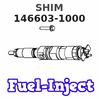
Information shim
BOSCH
9 461 610 450
9461610450
ZEXEL
146603-1000
1466031000
ISUZU
8942274980
8942274980
Rating:
Compare Prices: .
As an associate, we earn commssions on qualifying purchases through the links below

$10.98
24 Jan 2024
LV: Gear245
Bosch 9461610450 Shim
BOSCH
BOSCH
Include in ###:
Number on scheme 35/1

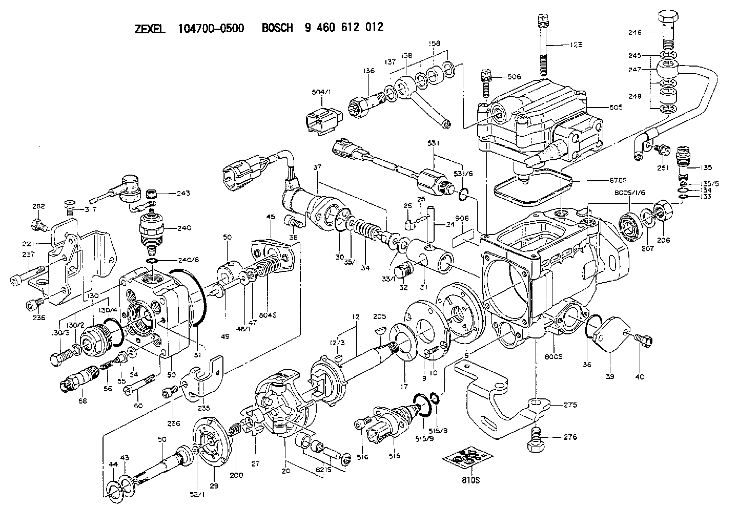
1047000500
as SHIM
D17.5&7.5T1.00
1047009153
as SHIM
1047009154
as SHIM
D17.5&7.5T1.00
Cross reference number
Zexel num
Bosch num
Firm num
Name
146603-1000
9 461 610 450
8942274980 ISUZU
SHIM
C 11FV SHIM parts(VE) Others
C 11FV SHIM parts(VE) Others
146603-1000
9 461 610 450
ME741819 MITSUBISHI
SHIM
C 11FV SHIM parts(VE) Others
C 11FV SHIM parts(VE) Others
146603-1000
9 461 610 450
16880V0703 NISSAN
SHIM
C 11FV SHIM parts(VE) Others
C 11FV SHIM parts(VE) Others
146603-1000
9 461 610 450
16880V0703 NISSAN-DIESEL
SHIM
C 11FV SHIM parts(VE) Others
C 11FV SHIM parts(VE) Others
146603-1000
9 461 610 450
093324068 MAZDA
SHIM
C 11FV SHIM parts(VE) Others
C 11FV SHIM parts(VE) Others
Information:
1. Remove shaft (2). Remove pin (1) from the shaft.2. Remove pins (3) from the flyweights. Remove flyweights (4). 3. Remove ring, races (6) and the bearing from riser (follower) (5). 4. Remove cover (7) and spring (8) from the governor housing. There is force on the cover from the spring.5. Remove seal (9) from the cover. 6. Remove cover (10) for the low and high idle adjustments.7. Remove locknut and screw (13) for the high idle adjustment.8. Remove bolt (15) and the washers for the low idle adjustment.9. Remove spring (16) and the guide.10. Remove pin (14) and plate (11).11. Remove shaft (12) from the housing. 12. Remove two spacers (17) and pin (18) from the shaft. 13. Remove shaft (19) from the governor housing.14. Remove washer (20) and levers (21) and (22) from the governor housing. 15. Remove seal (23) and the bearing.16. Remove seals (24) and (25) from the governor housing.Assemble Governor
1. Install the bearing and seal in the housing with tool (A). The lip of the seal must be toward the bearing. 2. Install seal (1) in housing with tool (A). The lip of the seal must be toward inside of housing.3. Install seal (2) in the housing with tool (B). The lip of the seal must be toward the inside of the housing. 4. Install shaft (3) in the housing. 5. Install plates (4), spacers (8) and pin (7) on shaft (5).6. Install shaft (5) in the housing and through washer (9) and levers (6). 7. Install pin (11) in the holes of the plates.8. Install screw (10) and the locknut for the high idle adjustment.9. Install spring (13) and the guide.10. Install bolt (12) and the washer for the low idle adjustment.11. Push plate and pin (11) over toward bolt (12) and tighten the bolt. 12. Install the seal in cover (14) with tooling (B). The lip of the seal must be toward the inside. 13. Install spring (15) in the cover. Install cover (14) on the housing.
Spring (15) must be installed with the end of the spring in the position shown.
14. Install the cover (16) for the idle adjustment screws. 15. Install bearing (19) between races (18) on riser (follower) (17). Install ring (20). Ring (20) holds the washers on the riser (follower).16. Install the pin in shaft (23). 17. Install flyweights (22) and pin (21).18. Install shaft (23) in the flyweight assembly.end by: a) connection of governor to fuel injection pump housingb) Make adjustment of fuel system setting (See Fuel System Setting in Testing and Adjusting.)
Have questions with 146603-1000?
Group cross 146603-1000 ZEXEL
Isuzu
146603-1000
9 461 610 450
8942274980
SHIM
Mitsubishi
146603-1000
9 461 610 450
ME741819
SHIM
Nissan
146603-1000
9 461 610 450
16880V0703
SHIM
Nissan-Diesel
146603-1000
9 461 610 450
16880V0703
SHIM
Mazda
146603-1000
9 461 610 450
093324068
SHIM