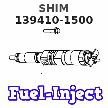
Information shim
BOSCH
9 411 610 206
9411610206
ZEXEL
139410-1500
1394101500
ISUZU
1157296180
1157296180
Rating:
Include in ###:
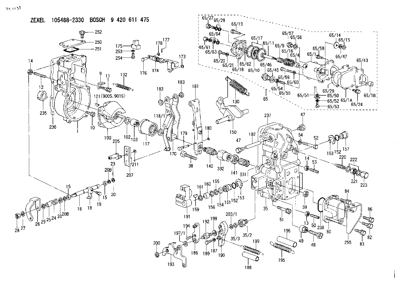
Number on scheme 168/1

1027520021
as SHIM
D26&10.2T0.9
1054600570
as SHIM
1054600572
as SHIM
D26&10.2T0.9
Cross reference number
Zexel num
Bosch num
Firm num
Name
139410-1500
9 411 610 206
1157296180 ISUZU
SHIM
C 90HY SHIM Standard parts Others
C 90HY SHIM Standard parts Others
139410-1500
9 411 610 206
228817190A HINO
SHIM
C 90HY SHIM Standard parts Others
C 90HY SHIM Standard parts Others
139410-1500
9 411 610 206
ME716757 MITSUBISHI
SHIM
C 90HY SHIM Standard parts Others
C 90HY SHIM Standard parts Others
139410-1500
9 411 610 206
1920889TA9 NISSAN
SHIM
C 90HY SHIM Standard parts Others
C 90HY SHIM Standard parts Others
139410-1500
9 411 610 206
19125Z9017 NISSAN-DIESEL
SHIM
C 90HY SHIM Standard parts Others
C 90HY SHIM Standard parts Others
139410-1500
9 411 610 206
SL0113V25 MAZDA
SHIM
C 90HY SHIM Standard parts Others
C 90HY SHIM Standard parts Others
139410-1500
9 411 610 206
SL0113T24 MAZDA
SHIM
A C 90HY SHIM Standard parts Others
A C 90HY SHIM Standard parts Others
Information:
Machine Preparation
Prepare the machine for maintenance.Refer to Operation and Maintenance Manual, SEBU8491, "Prepare the Machine for Maintenance".Removal Procedure
Illustration 2 g06215589
(A) 383-2040 Guard
(B) 8T-4195 Bolt
(C) 8T-4121 Hard Washer
(D) 384-0966 Insert
Remove and save the DEF guard (A), three bolts (B), three hard washers (C), and three inserts (D).
Illustration 3 g06217988
(C) 8T-4121 Hard Washer
(E) 368-4513 Side Plate
(F) 365-2227 Hose As
(G) 8T-4136 Bolt
(H) 1S-0994 Clip
(J) 8T-4137 Bolt
(K) 1S-1015 Clip
(L) 7K-1181 Cable Strap
Illustration 4 g06217851
(E) 368-4513 Side Plate
Illustration 5 g06219874
View of Area M
(C) 8T-4121 Hard Washer
(H) 1S-0994 Clip
(N) 399-3078 Machine Software Gp
(P) 434-1305 Insulation
(R) 326-4516 Cable Tie
(S) 8T-4195 Bolt
(T) 7X-7729 Washer
(U) 8T-4133 Nut
Remove six hard washers (C), two bolts (G), five clips (H), two bolts (J), clip (K), four cable straps (L), five cable ties (R), protective insulation (P), two bolts (S), two washers (T), and two nuts (U) from the hose assembly (F). Discard five clips (H), clip (K), five cable ties (R). Retain the rest of the parts.
Remove and discard hose assembly (F) from DEF tank and DEF Injector Mounting Gp (N). Refer to Illustration 3 and Illustration 5.Installation Procedure
Illustration 6 g06215872
(C) 8T-4121 Hard Washer
(G) 8T-4136 Bolt
(J) 8T-4137 Bolt
(1) 471-4171 Hose As
(2) 1S-0994 Clip
(3) 7K-1181 Cable Strap
(4) 1S-1015 Clip
Illustration 7 g06219875
View of Area M
(C) 8T-4121 Hard Washer
(N) 399-6078 DEF Injector & Mounting Gp
(P) 434-1305 Insulation
(S) 8T-4195 Bolt
(T) 7X-7729 Washer
(U) 8T-4133 Nut
(1) 471-4171 Hose As
(2) 1S-0994 Clip
(5) 326-4516 Cable Tie
Install new hose assembly (1) to the DEF tank and DEF injector mounting group (N). Secure hose assembly (1) using five clips (2), four cable straps (3), clip (4), six hard washers (C), two bolts (G), two bolts (J), two bolts (S), two washers (T), and two nuts (U) that were saved in Step 2 of Section "Removal Procedure". Refer to Illustration 6 and Illustration 7.
Secure protective insulation (P) that was saved in Step 2 of Section "Removal Procedure" to hose assembly (1) using five cable ties (5). Refer to Illustration 7.
Illustration 8 g06215593
(A) 383-2040 Guard
(V) Template
Illustration 9 g06215595
(X) 94.4 mm (3.72 inch)
(Y) 225 mm (8.9 inch)
Use Illustration 9 as a template and position the template onto guard (A), aligning to the edges. Trim the guard (A) according to the template. Refer to Illustration 8.Note: Lay the template flat on the guard. The trimmed area of the guard (A) is the curved area. The square cutout on the template is not to be cut, the square corner allows the template to lay flatter on the guard.
Illustration 10 g06215889
(A) 383-2040 Guard
(E) 368-4513 Side Plate
(1) 471-4171 Hose As
Install the modified DEF guard (A) using the hardware that was saved in Step 1 of Section "Removal Procedure".Note: Ensure adequate clearance has been obtained.
Return machine to service.
Have questions with 139410-1500?
Group cross 139410-1500 ZEXEL
Isuzu
139410-1500
9 411 610 206
1157296180
SHIM
Hino
139410-1500
9 411 610 206
228817190A
SHIM
Mitsubishi
139410-1500
9 411 610 206
ME716757
SHIM
Nissan
139410-1500
9 411 610 206
1920889TA9
SHIM
Nissan-Diesel
139410-1500
9 411 610 206
19125Z9017
SHIM
Mazda
139410-1500
9 411 610 206
SL0113V25
SHIM
139410-1500
9 411 610 206
SL0113T24
SHIM