Information shim
BOSCH
9 442 610 569
9442610569
ZEXEL
029312-0380
0293120380
ISUZU
5156290320
5156290320

Rating:
Include in #2:
104740-9870
as _
Include in ###:
Number on scheme 93A/1

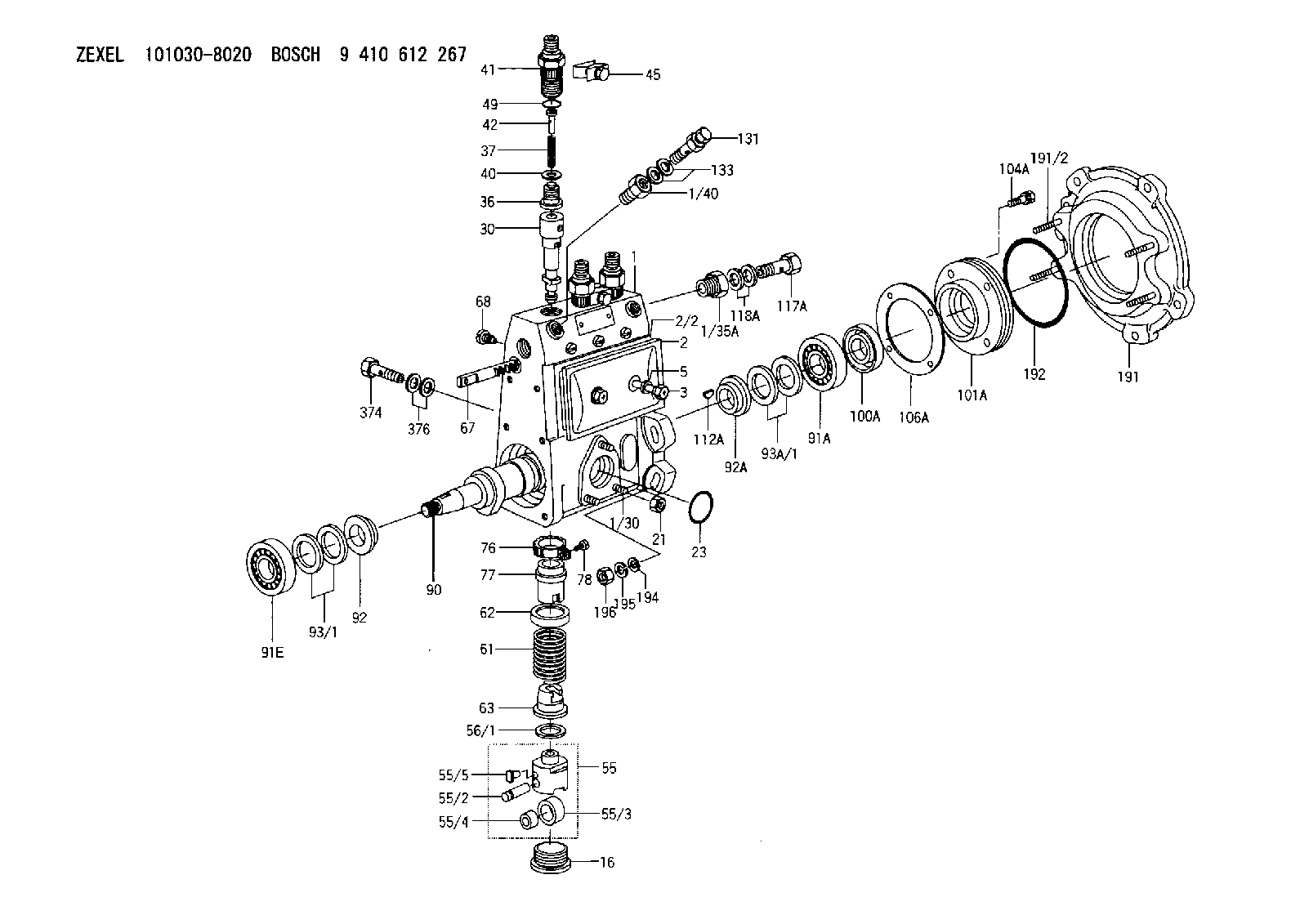
1010308020
as SHIM
D24&20T1.0
1010409231
as SHIM
1010409233
as SHIM
D24&20T1.0
1010499030
as SHIM
1010499031
as SHIM
D24&20T1.0
Cross reference number
Zexel num
Bosch num
Firm num
Name
029312-0380
9 442 610 569
5156290320 ISUZU
SHIM
D 90HY SHIM Standard parts Others
D 90HY SHIM Standard parts Others
029312-0380
9 442 610 569
228811700A HINO
SHIM
D 90HY SHIM Standard parts Others
D 90HY SHIM Standard parts Others
029312-0380
9 442 610 569
ME717985 MITSUBISHI
SHIM
D 90HY SHIM Standard parts Others
D 90HY SHIM Standard parts Others
029312-0380
9 442 610 569
16785Z9015 NISSAN-DIESEL
SHIM
D 90HY SHIM Standard parts Others
D 90HY SHIM Standard parts Others
Information:
Engine Electrical System
The electrical system can have three separate circuits: the charging circuit, the starting circuit and the low amperage circuit. Some of the electrical system components are used in more than one circuit. The battery (batteries), circuit breaker, ammeter, cables and wires from the battery are all common in each of the circuits.The charging circuit is in operation when the engine is running. An alternator makes electricity for the charging circuit. A voltage regulator in the circuit controls the electrical output to keep the battery at full charge.The starting circuit is in operation only when the start switch is activated.The low amperage circuit and the charging circuit are both connected through the ammeter. The starting circuit is not connected through the ammeter.Charging System Components
Alternator
The alternator is driven by V-type belts from the crankshaft pulley. This alternator is a three phase, self-rectifying charging unit, and the regulator is part of the alternator.This alternator design has no need for slip rings or brushes, and the only part that has movement is the rotor assembly. All conductors that carry current are stationary. The conductors are: the field winding, stator windings, six rectifying diodes, and the regulator circuit components.The rotor assembly has many magnetic poles like fingers with air space between each opposite pole. The poles have residual magnetism (like permanent magnets) that produce a small amount of magnet-like lines of force (magnetic field) between the poles. As the rotor assembly begins to turn between the field winding and the stator windings, a small amount of alternating current (AC) is produced in the stator windings from the small magnetic lines of force made by the residual magnetism of the poles. This AC current is changed to direct current (DC) when it passes through the diodes of the rectifier bridge. Most of this current goes to charge the battery and to supply the low amperage circuit, and the remainder is sent on to the field windings. The DC current flow through the field windings (wires around an iron core) now increases the strength of the magnetic lines of force. These stronger lines of force now increase the amount of AC current produced in the stator windings. The increased speed of the rotor assembly also increases the current and voltage output of the alternator.The voltage regulator is a solid state (transistor, stationary parts) electronic switch. It feels the voltage in the system and switches on and off many times a second to control the field current (DC current to the field windings) for the alternator to make the needed voltage output.
Never operate the alternator without the battery in the circuit. Making or breaking an alternator connection with heavy load on the circuit can cause damage to the regulator.
Alternator Components
(1) Regulator. (2) Roller bearing. (3) Stator winding. (4) Ball bearing. (5) Rectifier bridge. (6) Field winding. (7) Rotor assembly. (8) Fan.Starting System Components
Solenoid
Typical Solenoid SchematicA solenoid is an electromagnetic switch that does two basic operations.a. Closes the high current starter motor circuit with a
Have questions with 029312-0380?
Group cross 029312-0380 ZEXEL
Isuzu
Hino
Mitsubishi
Nissan
Nissan-Diesel
Mazda
M.Bishi-Hi.-Nag
Isuzu
Hino
Mitsubishi
Nissan-Diesel
Mazda
Isuzu
Hino
Mitsubishi
Nissan-Diesel
Mazda
Isuzu
Hino
Mitsubishi
Nissan-Diesel
Mazda
Isuzu
Hino
Mitsubishi
Nissan-Diesel
Mazda
Isuzu
Hino
Mitsubishi
Nissan-Diesel
Mazda
Isuzu
Hino
Mitsubishi
Nissan-Diesel
Isuzu
Hino
Mitsubishi
Nissan-Diesel
Isuzu
029312-0380
9 442 610 569
5156290320
SHIM
Hino
029312-0380
9 442 610 569
228811700A
SHIM
Mitsubishi
029312-0380
9 442 610 569
ME717985
SHIM
Nissan-Diesel
029312-0380
9 442 610 569
16785Z9015
SHIM