Information shim
BOSCH
9 442 610 442
9442610442
ZEXEL
029311-1120
0293111120
ISUZU
9813252880
9813252880
Rating:
Include in #2:
104740-2750
as _
Include in ###:
Number on scheme 115/45

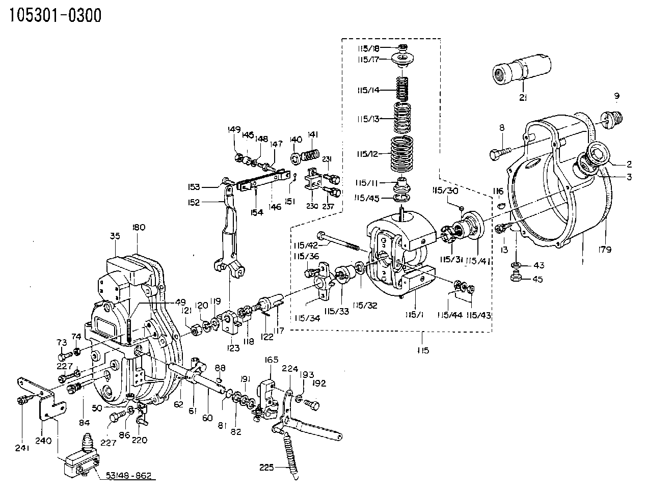
1053010300
as SHIM
D17&11T0.2
1054800660
as SHIM
1054800661
as SHIM
D17&11T0.2
1054870231
as SHIM
1054870233
as SHIM
D17&11T0.2
1054870391
as SHIM
1054870393
as SHIM
D17&11T0.2
1054870570
as SHIM
1054870610
as SHIM
D17&11T0.2
1054870850
as SHIM
1054870851
as SHIM
D17&11T0.2
1054870982
as SHIM
1054870983
as SHIM
D17&11T0.2
1054871050
as SHIM
1054871252
as SHIM
D17&11T0.2
Cross reference number
Zexel num
Bosch num
Firm num
Name
029311-1120
9 442 610 442
9813252880 ISUZU
SHIM
D 90HY SHIM Standard parts Others
D 90HY SHIM Standard parts Others
029311-1120
9 442 610 442
6073139660 HINO
SHIM
D 90HY SHIM Standard parts Others
D 90HY SHIM Standard parts Others
029311-1120
9 442 610 442
228814200A HINO
SHIM
A D 90HY SHIM Standard parts Others
A D 90HY SHIM Standard parts Others
029311-1120
9 442 610 442
228813890A HINO
SHIM
B D 90HY SHIM Standard parts Others
B D 90HY SHIM Standard parts Others
029311-1120
9 442 610 442
ME705336 MITSUBISHI
SHIM
D 90HY SHIM Standard parts Others
D 90HY SHIM Standard parts Others
029311-1120
9 442 610 442
1928399012 NISSAN-DIESEL
SHIM
D 90HY SHIM Standard parts Others
D 90HY SHIM Standard parts Others
Information:
1. Install the turbocharger on tool (A) as shown.2. Put alignment marks on three housings of the turbocharger for correct alignment during assembly. Loosen clamp (2), and remove the clamp and housing (1) from housing assembly (3). 3. Loosen clamp (4), and remove the housing assembly (3) from housing (5). 4. Put the cartridge group in position in tool (B) as shown.
When the nut is loosened, do not put a side force on the shaft. This can result in a bent shaft.
5. Use a 5S9566 Sliding T-Wrench and a universal socket (6) to remove the nut that holds the compressor wheel to the wheel assembly.6. Remove compressor wheel (7) and the shims from wheel assembly (8).7. Remove housing assembly (3) from wheel assembly (8). 8. Remove ring (9) and backplate (10) from wheel assembly (8). 9. Use tool (C), and remove snap ring (11) from housing assembly (3). 10. Remove insert (12) and sleeve (13) from housing assembly (3). 11. Remove ring (14) from sleeve (13). 12. Remove the screws (15) and deflector (16) from housing assembly (3). 13. Remove ring (18) and bearing assembly (17) from the housing assembly. 14. Remove sleeve (19) and ring (20) from the housing assembly. 15. Remove O-ring seal (23) from the housing assembly.16. Use tool (D), and remove snap ring (22) from the housing assembly.17. Remove bearing (21). Remove the snap ring behind the bearing with tool (D). 18. Use tool (D), and remove snap ring (25) from the housing assembly.19. Remove bearing (24). Remove the snap ring behind the bearing with tool (D).20. Check all the parts of the turbocharger for damage. If the parts are damaged, use new parts for replacement. See Special Instruction, Form No. SMHS6854 for Turbocharger Reconditioning. Also see Guidelines For Reusable Parts, Form No. SEBF8018.Assemble Turbocharger
1. Make sure that all of the oil passages in the turbocharger cartridge housing are clean and free of dirt and foreign material. Do not put oil on any parts of the turbocharger until after the compressor wheel has been installed. After the turbocharger has been assembled, pour clean engine oil into the oil inlet of the turbocharger.
Make sure that the snap rings that hold bearings (24) and (21) in position in housing assembly (3) are installed with round edge of the outside diameter toward the bearing.
2. Install the snap ring behind bearing (24) with tool (D).3. Install bearing (24) in housing assembly (3).4. Use tool (D), and install snap ring (25) in the housing assembly. 5. Install the snap ring behind bearing (21) with tool (D).6. Install bearing (21) in the housing assembly.7. Use tool (D), and install snap ring (22) in the housing assembly. 8. Put wheel assembly (8) in position on tool (B) as shown.9. Put backplate (10) in position on the wheel assembly. Put 6V2055 High Vacuum Grease in the groove for seal ring (9) at assembly to one half or more of the depth of the groove all the way around.10. Install ring (9) in
Have questions with 029311-1120?
Group cross 029311-1120 ZEXEL
Isuzu
029311-1120
9 442 610 442
9813252880
SHIM
Hino
029311-1120
9 442 610 442
6073139660
SHIM
029311-1120
9 442 610 442
228814200A
SHIM
029311-1120
9 442 610 442
228813890A
SHIM
Mitsubishi
029311-1120
9 442 610 442
ME705336
SHIM
Nissan-Diesel
029311-1120
9 442 610 442
1928399012
SHIM