Information shim
BOSCH
9 442 610 111
9442610111
ZEXEL
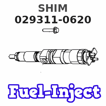
029311-0620
0293110620
ISUZU
5156191080
5156191080
Rating:
Include in ###:
Cross reference number
Zexel num
Bosch num
Firm num
Name
029311-0620
9 442 610 111
5156191080 ISUZU
SHIM
D 90HY SHIM Standard parts Others
D 90HY SHIM Standard parts Others
029311-0620
9 442 610 111
228815070A HINO
SHIM
D 90HY SHIM Standard parts Others
D 90HY SHIM Standard parts Others
029311-0620
9 442 610 111
228816670A HINO
SHIM
A D 90HY SHIM Standard parts Others
A D 90HY SHIM Standard parts Others
029311-0620
9 442 610 111
S228816670A HINO
SHIM
B D 90HY SHIM Standard parts Others
B D 90HY SHIM Standard parts Others
029311-0620
9 442 610 111
ME705181 MITSUBISHI
SHIM
D 90HY SHIM Standard parts Others
D 90HY SHIM Standard parts Others
029311-0620
9 442 610 111
16741T8276 NISSAN
SHIM
D 90HY SHIM Standard parts Others
D 90HY SHIM Standard parts Others
029311-0620
9 442 610 111
1671689TD0 NISSAN
SHIM
A D 90HY SHIM Standard parts Others
A D 90HY SHIM Standard parts Others
029311-0620
9 442 610 111
16741T8276 NISSAN-DIESEL
SHIM
D 90HY SHIM Standard parts Others
D 90HY SHIM Standard parts Others
029311-0620
9 442 610 111
SL0124167 MAZDA
SHIM
D 90HY SHIM Standard parts Others
D 90HY SHIM Standard parts Others
029311-0620
9 442 610 111
EZ40060XX052 M.BISHI-HI.-NAG
SHIM
D 90HY SHIM Standard parts Others
D 90HY SHIM Standard parts Others
Information:
Introduction:
This instruction is for removal and installation of the new 122-8842 Wiring Harness for the IAPCV on these engines. This harness is intended for service replacement of the section of the 122-8835 Wiring Harness that serves only the IAPCV.Installation:
A. Remove The Failed Harness
1. Remove the section of failed harness:2. Locate the IAPCV at the inboard rear and top of the high pressure hydraulic pump. The pump is mounted to the back of the front cover on the upper left side of the engine, as seen from the driver's seat, (illustration 1 and 2).3. Gently pry open the "ears" (illustration 4), that retain the 2-pin electrical connector in place, and unplug the harness from the 122-5053 IAPCV.4. Remove the harness tie wraps from the IAPCV back to connector P2. There is one tie a few inches below the connector (illustration 1 and 2), and two more along the engine block toward the rear.
Illustration 1. High pressure hydraulic pump (1), 2-pin Packard Electrical Connector (2), tie wraps (3), 40-pin connector P2 (4), 40-pin connector J2 (5).
Illustration 2. Hydraulic pump (6), IAPCV (7), tie wrap (8), Fuel Transfer Pump Gp (9).5. On early production engines the 122-8835 Wiring Harness is one piece. If so, cut the IAPCV Sensor Wires where they emerge from the braid at the sensor end. On later engines, the harness has four separate sections.6. Remove the 40-pin connector P2 from J2 on the ECM by unscrewing the M5 Allen Head Screw from the rear of J2.7. Using the 121-9588 Deutsch Pin Removal Tool (medium blue, for #16 and #18 gauge wires), remove the two pins from P2 (illustration 3). Insert wire removal tool without twisting.8. Remove the pink wire from P2 pin-19 and the black wire from P2 Pin-13. Cut these two wires where they emerge from the braid near P2.B. Install New 122-8842 Wiring Harness:
Illustration 3. P2 pin-13 (1), P2 pin-19 (2), P2 harness side of 40-pin connector (3), J2 ECM side of 40-pin connector (4), M5 Allen Head Screw (5).1. Install harness in reverse order of removal. Begin by inserting the pink wire pin into P2 pin-19 and black wire pin into P2 pin-13. After inserting, use the 45 N (10 lb) pull test, to verify that the connection is secure.2. Blend the two wires from the replacement harness in with all the other wires coming from P2 and install a tie wrap about three inches from P2.3. Route the replacement IAPCV Harness along with the old harness (which still contains the two twisted pairs going to the Speed Timing Sensors) until forward of the second secured tie wrap. Be sure the wires are routed next to the block, between the block and the oil feed tube to the hydraulic oil pump.4. Use tie wraps to bind the replacement harness to the old harness. Be sure new tie wraps are installed around both harnesses in the three locations that are secured to the block. Use as many additional unsecured tie wraps as necessary to bind
Have questions with 029311-0620?
Group cross 029311-0620 ZEXEL
Isuzu
029311-0620
9 442 610 111
5156191080
SHIM
Hino
029311-0620
9 442 610 111
228815070A
SHIM
029311-0620
9 442 610 111
228816670A
SHIM
029311-0620
9 442 610 111
S228816670A
SHIM
Mitsubishi
029311-0620
9 442 610 111
ME705181
SHIM
Nissan
029311-0620
9 442 610 111
16741T8276
SHIM
029311-0620
9 442 610 111
1671689TD0
SHIM
Nissan-Diesel
029311-0620
9 442 610 111
16741T8276
SHIM
Mazda
029311-0620
9 442 610 111
SL0124167
SHIM
M.Bishi-Hi.-Nag
029311-0620
9 442 610 111
EZ40060XX052
SHIM