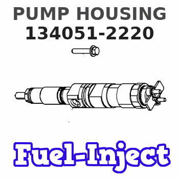
Information pump housing
BOSCH
9 411 613 700
9411613700
ZEXEL
134051-2220
1340512220
MITSUBISHI
ME704373
me704373
Rating:
Include in ###:
Cross reference number
Zexel num
Bosch num
Firm num
Name
134051-2220
9 411 613 700
ME704373 MITSUBISHI
PUMP HOUSING
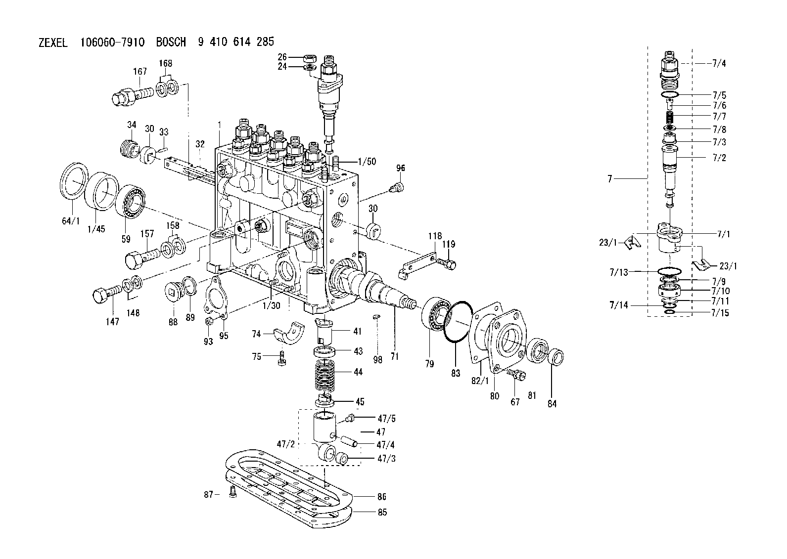
K 14FR HOUSING;PUMP parts(P,PD) Others
K 14FR HOUSING;PUMP parts(P,PD) Others
Information:
Tighten locknuts (A) on rod ends to ... 12 4 N m (9 3 lb ft)With governor at High Idle, install lever (B) on governor shaft at an angle from vertical of ... 20 5°Dimension (C) approximately ... 438.0 mm (17.25 in)Dimension (D) approximately ... 597.0 mm (23.50 in)Dimension (E) approximately ... 610.0 mm (24.00 in)Dimension (F) approximately ... 100.00 mm (3.94 in)Dimension (G) ... 1.5 mm (.06 in)Adjust bolt (H) to get dimension (F) with engine at High IdleAdjust setscrew (J) so that engine speed is 985 50 rpm with decelerator pedal depressed. Check High Idle speed after adjustment.After linkage has been adjusted, move control lever to High Idle and adjust setscrew (K) to get dimension (G).D7G With Direct Drive Transmission & 571G Pipelayer
Tighten locknuts (A) on ends to ... 12 4 N m (9 3 lb ft)With governor at High Idle, install lever (B) on governor shaft at an angle from vertical of ... 20 5°Dimension (C) approximately ... 438.0 mm (17.25 in)Dimension (D) approximately ... 597.0 mm (23.50 in)572G Pipelayer
Tighten locknuts (A) on rod ends to ... 12 4 N m (9 3 lb ft)With governor at High Idle, install lever (B) on governor shaft at an angle from vertical of ... 5° 5°Dimension (C) approximately ... 726.4 mm (28.6 in)Dimension (D) approximately ... 683.3 mm (26.9 in)7G5554 Control Group (D6H)
1. Tighten locknuts (A) on rod ends to ... 14 4 N m (10 3 lb ft)2. Align the timing mark on shaft (B) with centerline of sawcut on lever (C).3. Dimension (D) approximately ... 508 mm (20 in)4. With governor control lever in a vertical position, angle (E) ... 32° 5°3T4347 Control Group (D6H)
1. Tighten locknuts (A) on rod ends to ... 14 4 N m (10 3 lb ft)2. Align the timing mark on shaft (B) with centerline of sawcut on lever (C).3. Dimension (D) approximately ... 508 mm (20 in)4. With governor control lever in a vertical position, angle (E) ... 32° 5°6T3303 Control Group (D7H)
1. Tighten locknuts (A) on rod ends to ... 12 4 N m (9 3 lb ft)2. Align the timing mark on shaft (B) with centerline of sawcut on lever (C).3. With governor control lever in a vertical position, angle (E) ... 32° 5°8P3126 Control Group (D5B SA)
1. With control lever (1) in high idle position Dimension (A) approximately ... 495.0 mm (19.5 in)Dimension (B) approximately ... 786.0 mm (30.9 in)Angle (C) from vertical ... 10° 5°2. Tighten locknuts (2) on rod ends to ... 25 7 N m (18 5 lb ft)3. Tighten locknuts (3) on rod ends to ... 12 4 N m (9 3 lb ft)9W3764 Control Group (D6D SA)
1. With control lever (1) in high idle position Dimension (A) approximately ... 495.0 3.0 mm (19.5 .1 in)Dimension (B) approximately ... 735.0 mm (28.9 in)Angle (C) from vertical
Have questions with 134051-2220?
Group cross 134051-2220 ZEXEL
Mitsubishi
134051-2220
9 411 613 700
ME704373
PUMP HOUSING