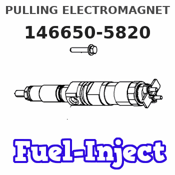
Information pulling electromagnet
BOSCH
9 461 615 275
9461615275
ZEXEL
146650-5820
1466505820
ISUZU
8970323920
8970323920
Rating:
Compare Prices: .
As an associate, we earn commssions on qualifying purchases through the links below

Tendparts Solenoid Valve 12V 8970323920 9461615275 Compatible with Isuzu 4JB1 Compatible with Bosch Compatible with Zexel
Tendparts Part Numbers: 146650-5820 8970323920 9461615275 || Compatible with Isuzu 4JB1 Compatible with Bosch Compatible with Zexel || Package Includes: 1x Solenoid Valve || Easy To Install. Manufactured to Precise OE Requirements For Perfect Fit. Reliable Performance. || Replacement Parts. As Good As OEM at a Fraction of the Price. Exact Same Performance as Original
Tendparts Part Numbers: 146650-5820 8970323920 9461615275 || Compatible with Isuzu 4JB1 Compatible with Bosch Compatible with Zexel || Package Includes: 1x Solenoid Valve || Easy To Install. Manufactured to Precise OE Requirements For Perfect Fit. Reliable Performance. || Replacement Parts. As Good As OEM at a Fraction of the Price. Exact Same Performance as Original

Heavy Equipment Parts & Accessories – Durable High-Performance Replacement Parts 12V Solenoid Valve 146650-5820 8970323920 9461615275 for Isuzu Nissan Ud Yanmar Model-Z59-FX2451
Generic ✔ Premium Quality & Durability – Manufactured with high-grade materials to ensure long-lasting performance in demanding industrial and construction environments. || ✔ Wide Compatibility – Designed to fit various heavy equipment brands and models, including excavators, loaders, bulldozers, and more for seamless installation. || ✔ Enhanced Performance & Efficiency – Engineered to withstand extreme conditions, reducing downtime and increasing the lifespan of your machinery. || ✔ Easy Installation & Maintenance – Precise fitment and hassle-free setup make replacements quick and efficient, saving time and labor costs. || ✔ Reliable Supplier – Sourced from trusted manufacturers with strict quality control standards, ensuring timely superior product reliability.
Generic ✔ Premium Quality & Durability – Manufactured with high-grade materials to ensure long-lasting performance in demanding industrial and construction environments. || ✔ Wide Compatibility – Designed to fit various heavy equipment brands and models, including excavators, loaders, bulldozers, and more for seamless installation. || ✔ Enhanced Performance & Efficiency – Engineered to withstand extreme conditions, reducing downtime and increasing the lifespan of your machinery. || ✔ Easy Installation & Maintenance – Precise fitment and hassle-free setup make replacements quick and efficient, saving time and labor costs. || ✔ Reliable Supplier – Sourced from trusted manufacturers with strict quality control standards, ensuring timely superior product reliability.
Include in ###:
Cross reference number
Zexel num
Bosch num
Firm num
Name
146650-5820
9 461 615 275
8970323920 ISUZU
PULLING ELECTROMAGNET
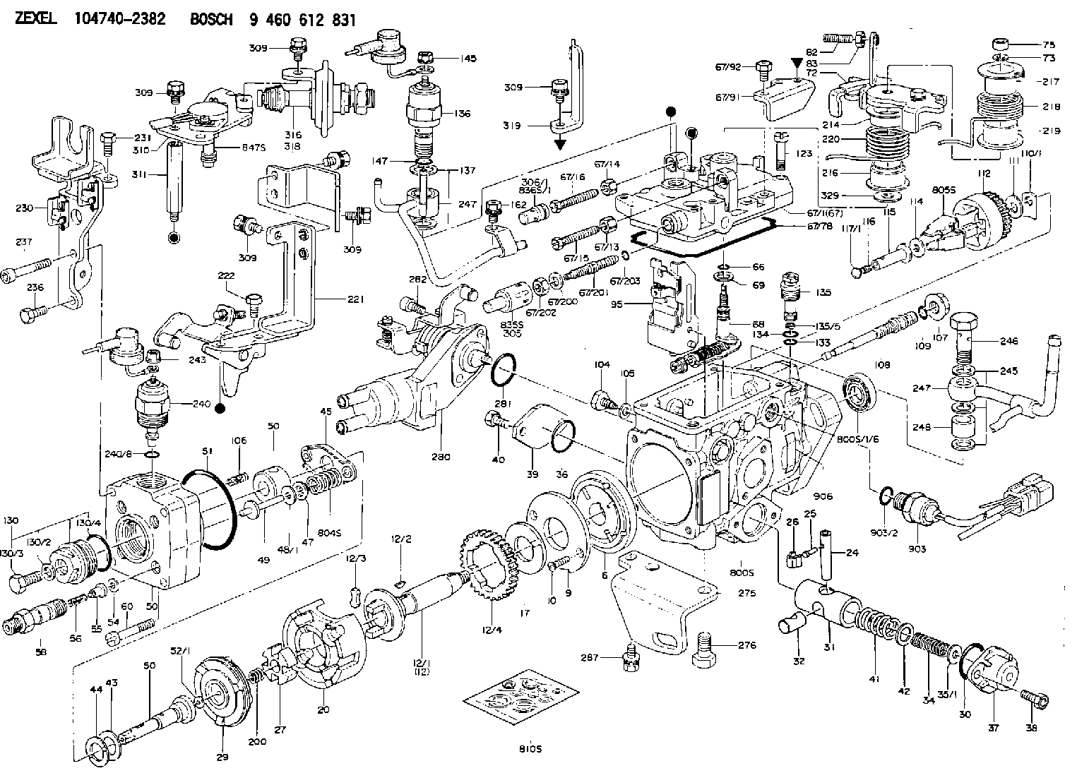
C 11FV MAGNET VALVE parts(VE) Others
C 11FV MAGNET VALVE parts(VE) Others
146650-5820
9 461 615 275
1689069T00 NISSAN
PULLING ELECTROMAGNET
C 11FV MAGNET VALVE parts(VE) Others
C 11FV MAGNET VALVE parts(VE) Others
146650-5820
9 461 615 275
1689079P01 NISSAN-DIESEL
PULLING ELECTROMAGNET
C 11FV MAGNET VALVE parts(VE) Others
C 11FV MAGNET VALVE parts(VE) Others
Information:
Install Tooling (E). Tighten Tooling (E) to a torque of 9 1 N m (80 9 lb in).Note: The pump will not function while Tooling (E) is installed. Running the fuel injection pump with the tooling installed will result in pump damage and system contamination.
Illustration 6 g02025176
Disconnect harness assemblies (3).
Remove nut (5) and remove the clamp assembly. Discard the clamp assembly.
Loosen nuts (4) and (7). Remove the fuel line and discard the fuel line.
Disconnect hose assembly (6).
Illustration 7 g02029098
Disconnect tube assemblies (9).
Disconnect hose assemblies (10) and (11).
Remove bolts (8).
Illustration 8 g02029093
Disconnect tube assembly (12).
Illustration 9 g02025262
Remove bolts (13) and remove fuel pump (14).Installing the Fuel Injection Pump
Note: Check the O-ring seals, the gaskets, and the seals for wear or for damage. Replace the components, if necessary.
Illustration 10 g02385860
Service replacement pump
Note: Service replacement pump is shipped pinned with warning tag (Z) installed under pinch bolt (E).
Illustration 11 g02025262
Position fuel pump (14) and install bolts (13).
Illustration 12 g02029093
Connect tube assembly (12).
Illustration 13 g02029098
Install bolts (8).
Connect tube assembly (9) and connect both hose assemblies (10) and (11).
Illustration 14 g02025176Note: During installation, make sure that the fuel line caps remain in position until the fuel line is positioned near the corresponding ports in order to prevent contamination. Ensure that the areas around the rail and fuel lines are thoroughly clean before continuing this procedure. If any parts are worn or damaged, use new parts for replacement. Cleanliness is an important factor. Ensure that no debris gets introduced into the fuel system during the installation procedure. If any parts are worn or damaged, use new parts for replacement.
Connect harness assemblies (3).
Install a new fuel line. Hand tighten nuts (4) and (7).
Position the clamp assembly and install nut (5). Hand tighten the nut. Failure to place the grommet correctly on the fuel line could result in a failed fuel line.Note: Ensure that the fuel lines are centered in the nuts prior to tightening. Do not use excessive force or bending in order to assemble the fuel lines.
Tighten nut (4) at the fuel rail to a torque of 27 3 N m (239 27 lb in).
Tighten nut (7) to a torque of 27 3 N m (239 27 lb in).
Tighten nut (5) to a torque of 12 3 N m (105 27 lb in).
Illustration 15 g02351995
Remove Tooling (E) and warning tag (Z).Note: The pump will not function while Tooling (E) is installed. Running the fuel injection pump with the tooling installed will result in pump damage and system contamination.
Illustration 16 g02351981
Install O-ring seal (2) and plug (1). Tighten the plug to a torque of 9 1 N m (80 9 lb in).
Illustration 17 g02112896
Remove all tooling. Reinstall plug (X) into the timing hole that is located in the flywheel housing.
Connect Caterpillar Electronic Technician (ET). Perform a “Fuel System Functional Test ”and a “Fuel System Verification Test”.
Have questions with 146650-5820?
Group cross 146650-5820 ZEXEL
Isuzu
146650-5820
9 461 615 275
8970323920
PULLING ELECTROMAGNET
Nissan
146650-5820
9 461 615 275
1689069T00
PULLING ELECTROMAGNET
Nissan-Diesel
146650-5820
9 461 615 275
1689079P01
PULLING ELECTROMAGNET