Information potentciometer
BOSCH
9 461 620 183
9461620183
ZEXEL
146685-2510
1466852510
NISSAN-DIESEL
168403S301
168403s301
Rating:
Include in ###:
Cross reference number
Zexel num
Bosch num
Firm num
Name
146685-2510
9 461 620 183
168403S301 NISSAN-DIESEL
POTENTCIOMETER
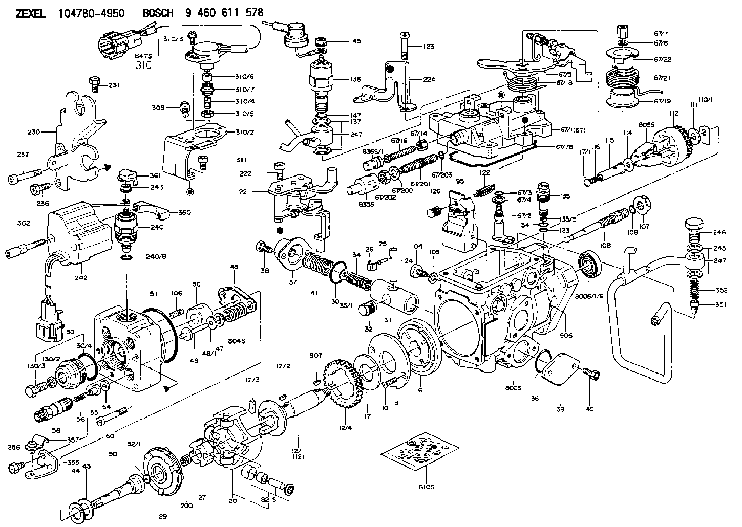
C 11FV POTENTIO METER parts(VE) Others
C 11FV POTENTIO METER parts(VE) Others
Information:
To avoid possible engine damage or another immediate shutdown, the water temperature fault must be corrected before attempting to restart the engine.
Even though the starter motor circuit can now be engaged, there is no fuel flow to the engine. The fuel flow to the engine is stopped until the coolant temperature falls below the rating for the water temperature contactor switch (WTS). When the coolant temperature falls below the rating for the water temperature contactor switch (WTS), the contactor switch opens again. The fuel shutoff solenoid is de-energized when the switch reopens. This allows fuel flow to the engine. The engine can then be restarted.2301A Electric Governor Control
The 2301A Electric Governor Control activates all of the components that are in the electric protection system. The components are activated in the same manner when the nonelectric governor is used. One difference exists in the main circuit. The fuel shutoff solenoid (FSOS) (line 43) is not used.When the electric governor control is used, the engine must run in a normal condition in order for the electric circuit to operate in the manner that is described below.
Current flows from the terminals (TS-28) (line 43) and (TS-31) (line 44), which are located on the terminal strip in the junction box.
Current from terminals (TS-28) (line 43) and (TS-31) (line 44) flows through the preregulator (PR) (line 48) or the fuse (F4) to the electric governor control.
When the engine flywheel is rotating, the current also flows through the electric governor actuator (EGA) (line 52). When a fault in the system causes the current to energize the slave relay (SR1), the following events occur in the electric circuit in order to stop the engine.
The slave relay (SR1) opens across the contacts (SR1-30) and (SR1-87a) (line 45). The relay closes across the contacts (SR1-30) and (SR1-87) (line 43).
When the circuit opens across contacts (SR1-30) and (SR1-87a), the current is stopped to the electric governor control.
Current to the electric governor actuator (EGA) is also stopped.
The mechanical spring load in the electric governor actuator (EGA) will now move the fuel control rod in order to stop fuel flow to the engine.Note: With the exception of the differences that are described in this section of the manual, all of the fault circuits in the electric protection system are identical for the 2301A Electric Governor Control and for the nonelectric governor control.
Illustration 3 g00292518
Junction Box Wiring for ETS with OP, WT,
Have questions with 146685-2510?
Group cross 146685-2510 ZEXEL
Nissan-Diesel
146685-2510
9 461 620 183
168403S301
POTENTCIOMETER