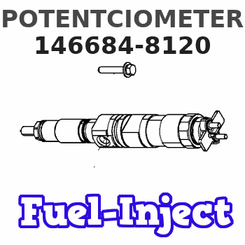
Information potentciometer
BOSCH
9 461 617 221
9461617221
ZEXEL
146684-8120
1466848120
Rating:
Include in ###:
Cross reference number
Zexel num
Bosch num
Firm num
Name
146684-8120
9 461 617 221
POTENTCIOMETER
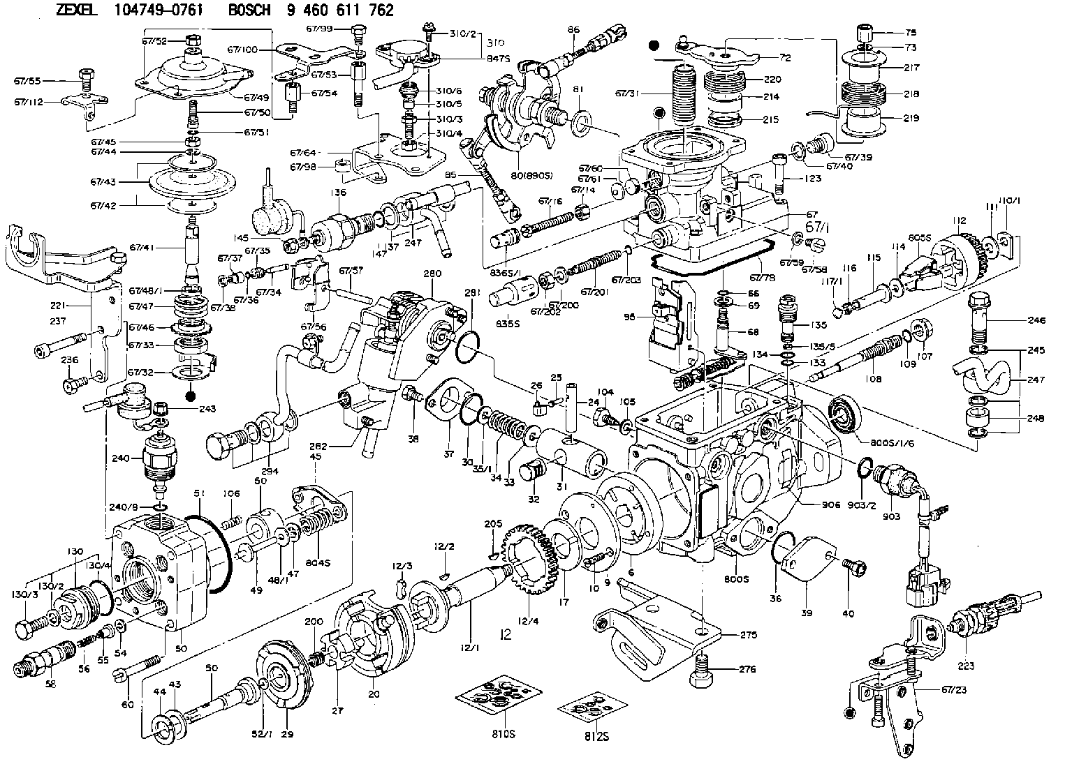
K 11FV POTENTIO METER parts(VE) Others
K 11FV POTENTIO METER parts(VE) Others
Information:
Image1.1.1
Image1.1.2
Image1.1.3
Image1.1.4
Image1.1.5
Image1.1.6
Image1.1.7
Image1.1.8
Image1.1.9
PROCEDURES FOR DPF MODULE REWORK
PROCEDURE ( A ) See Image 1.2.1
Butt weld ring flush to retainer ring on the inlet assembly in 4 spots.
Fillet weld (3 mm weld size) 4 tabs (at 0, 90,180 and 270 degrees.
PROCEDURE ( B ) See Image 1.2.2
Butt weld ring flush to retainer ring on the inlet assembly in 4 spots.
Fillet weld (3 mm weld size) 4 tabs (at 0, 90,180 and 270 degrees.
PROCEDURE ( C ) See Image 1.2.3
Butt weld ring flush to retainer ring on the inlet assembly in 4 spots.
Fillet weld (3 mm weld size) 4 tabs (at 0, 90,180 and 270 degrees.
PROCEDURE ( D ) See Image 1.2.4
Butt weld ring flush to retainer ring on the inlet assembly in 4 spots.
Fillet weld (3 mm weld size) 4 tabs (at 0, 90,180 and 270 degrees.
PROCEDURE ( E ) See Image 1.2.5
Butt weld ring flush to retainer ring on inlet assembly in 4 spots.
Fillet weld 2 pins (at 0 and 180 degree orientation) to outlet side of DPF's 300 mm from each other.
Drill 5/8" holes in the outlet assembly flanges 300 mm from each other.
Place tube flush to the flange inside this hole and weld to outlet assembly.
PROCEDURE ( F ) See Image 1.2.6
Position plates (at 0 and 180 degree orientation) to outlet side of the DPF flange.
Allow plates to extend ( minimum 1/4 inch ) past outer edge. Using slots in plates
weld into place.
PROCEDURE ( G ) See Image 1.2.7
Fillet weld (3 mm weld size) 2 pins (at 0 and 180 degree orientation) to outlet side of DPF 260 mm from each other.
Drill a 5/8" hole in the outlet assembly flange 260 mm from each other 13 mm deep.
Place tube flush to the flange inside this hole and weld to outlet assembly.
PROCEDURE ( H ) See Image 1.2.8
Fillet weld 2 pins (at 0 and 180 degree orientation) to outlet side of both DPF's 300 mm from each other.
Drill 5/8" holes in the outlet assembly flanges 300 mm from each other 13 mm deep.
Place tubes flush to the flange inside this hole and weld to outlet assembly.
PROCEDURE ( I ) See Image 1.2.9 and Image 1.2.10
Remove the clamp and gasket from DPF inlet side.
Mate inlet flange to DPF without gasket or clamp.
Tack weld in place.
Apply a continuous weld to the inlet flange/DPF seam.
Image1.2.1
Image1.2.2
Image1.2.3
Image1.2.4
Image1.2.5
Image1.2.6
Image1.2.7
Image1.2.8
Image1.2.9
Image1.2.10
Filter Module Cross Reference Guide See Image 1.3.1.
Image1.3.1
Have questions with 146684-8120?
Group cross 146684-8120 ZEXEL
146684-8120
9 461 617 221
POTENTCIOMETER