Information potentciometer
BOSCH
9 461 623 052
9461623052
ZEXEL
146683-5400
1466835400

Rating:
Include in ###:
Cross reference number
Zexel num
Bosch num
Firm num
Name
146683-5400
9 461 623 052
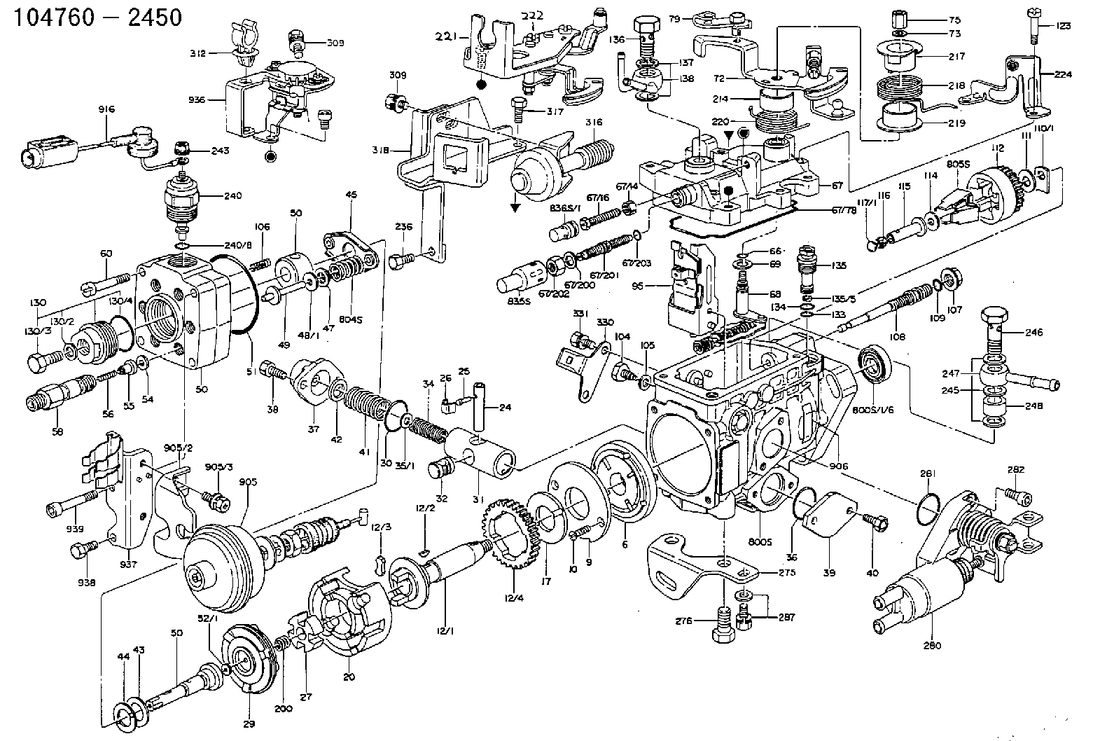
POTENTCIOMETER
C 11FV POTENTIO METER parts(VE) Others
C 11FV POTENTIO METER parts(VE) Others
Information:
2. Turn the crankshaft until two pistons are at bottom center.3. Remove nuts (1) and the bearing caps. Push the rods and pistons up until the rings are out of the cylinder liners. 4. Remove pistons (2) and connecting rods from the cylinder liners.5. Do Steps 1 through 4 for the remainder of the pistons and connecting rods.Install Pistons And Connecting Rod Assemblies
1. Put clean engine oil on piston rings, connecting rod bearings and cylinder liners. 2. Use tool (A), and install piston (2) and the connecting rod in the cylinder liner. Be sure the number on the tab groove side of the connecting rod is on the opposite side from the camshaft.3. Install the bearing cap on the connecting rod with the number on the side of the bearing cap on the same side and same number as on the connecting rod.4a. For connecting rods with bolts and nuts, use the following torque procedure: Apply clean engine oil to the bolt threads, nuts, and seating faces of the bearing cap. Tighten each nut to a torque of 80 5 N m (60 4 lb.ft.). Tighten each nut an additional 120° 5°.4b. For connecting rods with only bolts, use the following torque procedure: Apply Molylube to the threads of the bolts and to the seating faces of the bearing cap and the bolt. Tighten each bolt to a torque of 90 8 N m (66 6 lb.ft.). Tighten each bolt an additional 90° 5°.5. Do Steps 1 through 4 for the remainder of the pistons and connecting rods.End By:a. install oil pumpb. install cylinder head assembly.Disassemble And Assemble Pistons And Connecting Rod Assemblies
Start By:a. remove pistons and connecting rod assemblies 1. Remove bearings (3) from the connecting rod and connecting rod cap.2. Remove retainer ring (1) and tool (A).3. Remove pin (2) and connecting rod (4) from the piston. 4. Remove piston rings (5) from the piston with tool (B). Clean the piston ring grooves on the pistons with an acceptable ring groove cleaning tool. See, Use Of Piston Pin Bearing Removal And Installation Tools, Special Instructions, Form No. SMHS7295.5. Heat connecting rod (4) in an oven to a temperature of 177° to 260° C (350° to 500° F). Never use a direct flame to heat a connecting rod. 6. Put connecting rod (4) in position on the base plate of tooling (C). Put a new rod pin bearing (6) on the adapter part of tooling (C). The old bearing is pushed out by tooling (C) as the new bearing is installed.7. Use tooling (C) to push the new bearing into the connecting rod until the push adapter of tooling (C) makes full contact with the connecting rod surface.8. Use a pin boring machine to make the rod pin bearing the correct size. The bore in the new rod pin bearing must be 50.830 0.008 mm (2.0012 .0003 in.).9. Check the clearance between the ends of the piston rings. See
Have questions with 146683-5400?
Group cross 146683-5400 ZEXEL
146683-5400
9 461 623 052
POTENTCIOMETER