Information pneumatic governor
BOSCH
F 019 Z1E 815
f019z1e815
ZEXEL
105510-8490
1055108490
Rating:
Scheme ###:
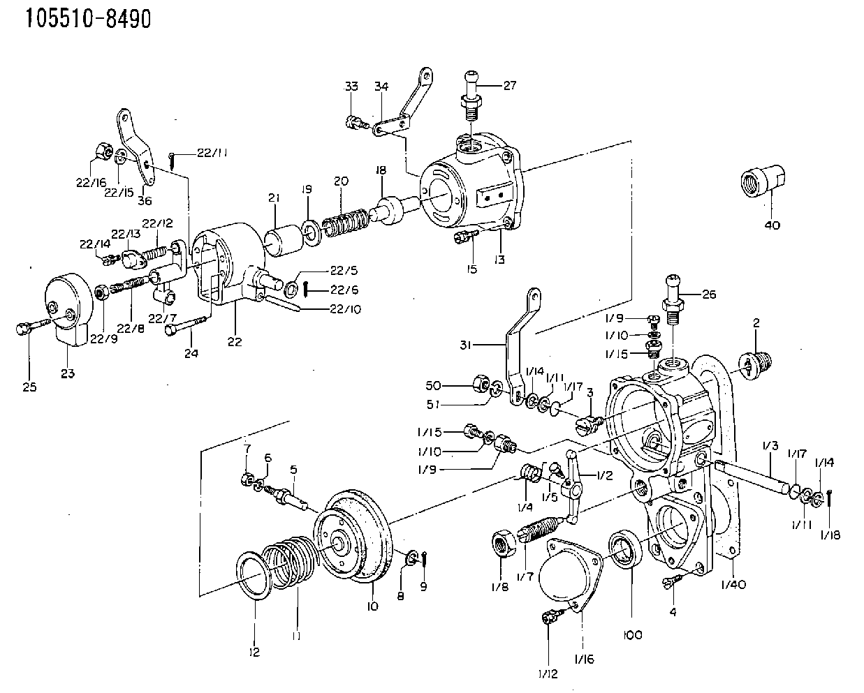
| 1. | [1] | 155000-1220 | GOVERNOR HOUSING |
| 1/1. | [1] | 155001-0720 | GOVERNOR HOUSING |
| 1/2. | [1] | 155003-0700 | CONTROL LEVER |
| 1/3. | [1] | 155004-1200 | LEVER SHAFT |
| 1/4. | [1] | 155005-0100 | COILED SPRING |
| 1/5. | [1] | 155006-0700 | BLEEDER SCREW |
| 1/7. | [1] | 155007-0120 | HEADLESS SCREW |
| 1/8. | [1] | 155011-0100 | HEXAGON NUT |
| 1/9. | [2] | 029010-6010 | CAPSULE M6P1.0L7 |
| 1/9. | [2] | 029010-6010 | CAPSULE M6P1.0L7 |
| 1/10. | [2] | 026506-1040 | GASKET D9.9&6.2T1 |
| 1/10. | [2] | 026506-1040 | GASKET D9.9&6.2T1 |
| 1/11. | [0] | 029310-8010 | PLAIN WASHER D15&8.4T0.2 |
| 1/11. | [0] | 029310-8010 | PLAIN WASHER D15&8.4T0.2 |
| 1/11B. | [0] | 029310-8020 | PLAIN WASHER D15&8.4T0.3 |
| 1/12. | [3] | 029010-6680 | BLEEDER SCREW |
| 1/14. | [2] | 029300-8010 | PLAIN WASHER D15&8T1.00 |
| 1/14. | [2] | 029300-8010 | PLAIN WASHER D15&8T1.00 |
| 1/14B. | [2] | 029300-8030 | PLAIN WASHER D15&8T1.50 |
| 1/15. | [2] | 155012-0100 | ADAPTOR |
| 1/15. | [2] | 155012-0100 | ADAPTOR |
| 1/16. | [1] | 155013-0100 | CAP |
| 1/17. | [2] | 029630-8030 | O-RING |
| 1/17. | [2] | 029630-8030 | O-RING |
| 1/18. | [2] | 025520-1210 | SPLIT PIN |
| 1/19. | [1] | 155402-9700 | PLATE |
| 2. | [1] | 154007-0200 | ADAPTOR |
| 3. | [1] | 020018-1840 | BLEEDER SCREW M8P1.25L18 |
| 4. | [4] | 021006-1540 | FLAT-HEAD SCREW |
| 5. | [1] | 153406-0400 | BLEEDER SCREW |
| 6. | [1] | 014110-5440 | LOCKING WASHER |
| 7. | [0] | 013020-5220 | |
| 7. | [1] | 013020-5240 | UNION NUT M5P0.8H4 |
| 8. | [1] | 023500-6210 | PLAIN WASHER D11&6.4T1.5 |
| 9. | [1] | 025520-1210 | SPLIT PIN |
| 10. | [1] | 155020-1420 | DIAPHRAGM |
| 11. | [1] | 155030-1000 | GOVERNOR SPRING |
| 12. | [0] | 155407-0500 | SHIM |
| 12B. | [0] | 155407-0600 | SHIM |
| 13. | [1] | 155041-0320 | GOVERNOR HOUSING |
| 15. | [4] | 020106-2240 | BLEEDER SCREW |
| 18. | [1] | 155043-0100 | STOP PIN |
| 19. | [1] | 155407-3300 | SHIM |
| 20. | [1] | 155045-1900 | COILED SPRING |
| 21. | [1] | 155044-0100 | GUIDE SLEEVE |
| 22. | [1] | 155050-8720 | GOVERNOR HOUSING |
| 22/1. | [1] | 155050-1500 | DIAPHRAGM HOUSING |
| 22/5. | [1] | 023500-8140 | PLAIN WASHER |
| 22/6. | [1] | 015330-1590 | SPLIT PIN |
| 22/7. | [1] | 155050-3300 | CONTROL LEVER |
| 22/8. | [1] | 155050-4100 | FLAT-HEAD SCREW |
| 22/9. | [1] | 013020-6020 | UNION NUT M6P1H5 |
| 22/10. | [1] | 155050-5100 | BEARING PIN |
| 22/11. | [1] | 025520-2010 | SPLIT PIN |
| 22/12. | [1] | 155050-6100 | COILED SPRING |
| 22/13. | [1] | 155050-7100 | CAP |
| 22/14. | [2] | 029050-4140 | FLAT-HEAD SCREW |
| 22/15. | [1] | 014110-8440 | LOCKING WASHER |
| 22/16. | [1] | 013020-8040 | UNION NUT M8P1.25H7 |
| 23. | [1] | 155051-0100 | COVER |
| 24. | [2] | 155051-2100 | BLEEDER SCREW |
| 25. | [2] | 020006-3240 | BLEEDER SCREW |
| 26. | [1] | 155616-0800 | JOINT CONNECTION |
| 27. | [1] | 155616-3020 | JOINT CONNECTION |
| 31. | [1] | 155414-6700 | CONTROL LEVER |
| 36. | [1] | 155414-6800 | CONTROL LEVER |
| 40. | [1] | 155404-3700 | CAP |
| 50. | [1] | 013020-8040 | UNION NUT M8P1.25H7 |
| 51. | [1] | 014110-8440 | LOCKING WASHER |
| 100. | [1] | 029621-7010 | PACKING RING |
| 140. | [1] | 154390-0000 | GASKET |
Include in #1:
101492-3310
as GOVERNOR
Cross reference number
Zexel num
Bosch num
Firm num
Name
Information:
Oil Pump
Disassembly and Inspection of Oil Pump
Measurement of Clearance Between Outer Rotor and Inner Rotor
Measure the clearance between the outer rotor and inner rotor, and, if the limit value is exceeded, replace the pump assembly.
Measurement of clearance between outer rotor and inner rotorMeasurement of Rotor and Case End Play
Measure the rotor and case end play, and, if the limit value is exceeded, replace the pump assembly.
Measurement of rotor and cover end playMeasurement of Clearance Between Outer Rotor and Pump Case
Measure the clearance between the outer rotor and pump case, and, if the limit value is exceeded, replace the pump assembly.
Measure the clearance between the outer rotor and caseReassembly of Oil Pump
Install the outer rotor to the pump case, check alignment mark (indentations) on the pump case cover, and then tighten the bolts. If the alignment marks are not aligned during the reassembly, the pump will not suck oil.
Alignment marks on pump case and pump case coverOil Filter and Oil Cooler
Inspection of Oil Filter, Oil Cooler and Relief Valve
Adjustment of Relief Valve
(1) Check the relief valve and valve seat for contact condition, and the spring for fatigue and damage, and replace any defective parts.(2) Measure the valve opening pressure (oil pressure when the engine is running at rated rpm) of the relief valve, and, if the standard valve is exceeded, remove the cap bolt and make an adjustment by increasing or decreasing the shim thickness.
Relief Valve