Information plunger-and-barrel assy
BOSCH
9 443 610 079
9443610079
ZEXEL
141170-0020
1411700020
NIIGATA-URAWA
V0C47020A
v0c47020a

Rating:
Include in ###:
Number on scheme 5

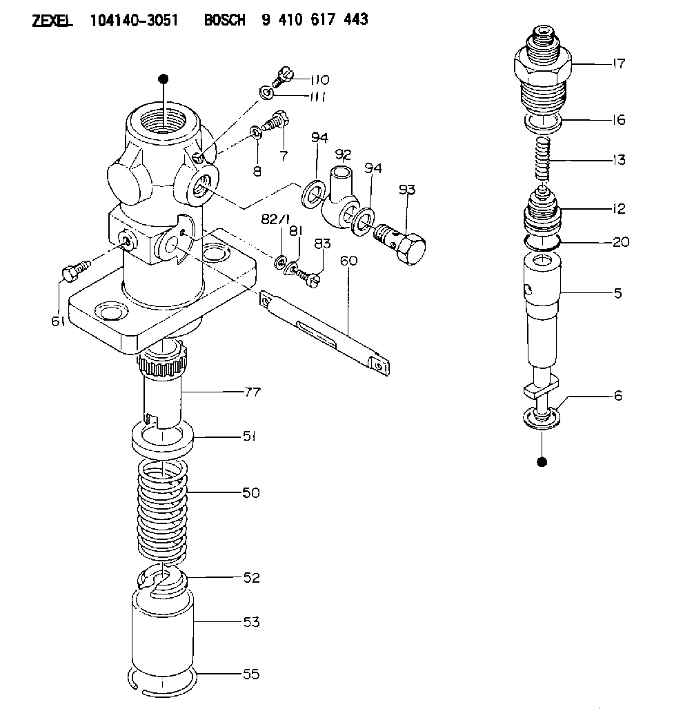
1041403051
as PLUNGER-AND-BARREL ASSY
1041403052
as PLUNGER-AND-BARREL ASSY
C25
1041403110
as PLUNGER-AND-BARREL ASSY
Cross reference number
Zexel num
Bosch num
Firm num
Name
141170-0020
V0C47020A NIIGATA-URAWA
PLUNGER-AND-BARREL ASSY
C 26FD PLUNGER ASSY PL(PF-C for marine) PL
C 26FD PLUNGER ASSY PL(PF-C for marine) PL
141170-0020
E226202190Z DAIHATSU
PLUNGER-AND-BARREL ASSY
C 26FD PLUNGER ASSY PL(PF-C for marine) PL
C 26FD PLUNGER ASSY PL(PF-C for marine) PL
141170-0020
3521724500 KUBOTA
PLUNGER-AND-BARREL ASSY
C 26FD PLUNGER ASSY PL(PF-C for marine) PL
C 26FD PLUNGER ASSY PL(PF-C for marine) PL
141170-0020
1722668500 KUBOTA
PLUNGER-AND-BARREL ASSY
A C 26FD PLUNGER ASSY PL(PF-C for marine) PL
A C 26FD PLUNGER ASSY PL(PF-C for marine) PL
141170-0020
V0C47020A NIIGATA-TEKKOU
PLUNGER-AND-BARREL ASSY
C 26FD PLUNGER ASSY PL(PF-C for marine) PL
C 26FD PLUNGER ASSY PL(PF-C for marine) PL
141170-0020
1722668500 KUBOTA
PLUNGER-AND-BARREL ASSY
C 26FD PLUNGER ASSY PL(PF-C for marine) PL
C 26FD PLUNGER ASSY PL(PF-C for marine) PL
Information:
start by: a) remove cylinder head1. Remove precombustion chambers and valve lifters. 2. Use tooling (A) to compress the valve spring. Remove locks that hold spring to valve stem.3. Remove tooling (A), the valve and spring assembly. 4. Inspect the valve seat insert. Measure the diameter of the valve stem. The minimum diameter of the stem is .3689 in. (9.37 mm). For 2M6402 and 2M6403 valves minimum diameter of valve stem is .3692 in. (9.378 mm). 5. Use tool (B) to measure valve spring force. Test force for valve springs is 55.0 3.5 lb. (244.65 15.57 N).6. The free length of spring is 2.31 in. (58.7 mm). The test length is 1.95 in. (49.5 mm). 7. Put clean engine oil on the valve stem. Install the washer, spring (1) and rotocoil (2). Install the valve through the valve guide.8. Install tooling (A) to put the valve spring under compression.
The valve spring must be put under compression just enough to permit the locks to be put in position on the valve stem.
9. Install the locks on the valve stem.
The locks can be thrown from the valve when the compressor is removed. Make certain the locks are in position before the valve compressor is removed.
10. Remove tooling (A) and hit the valve with a soft hammer to be sure that the locks make a seat on the valve stem.11. Install the valve lifters and precombustion chambers.end by: a) install cylinder head