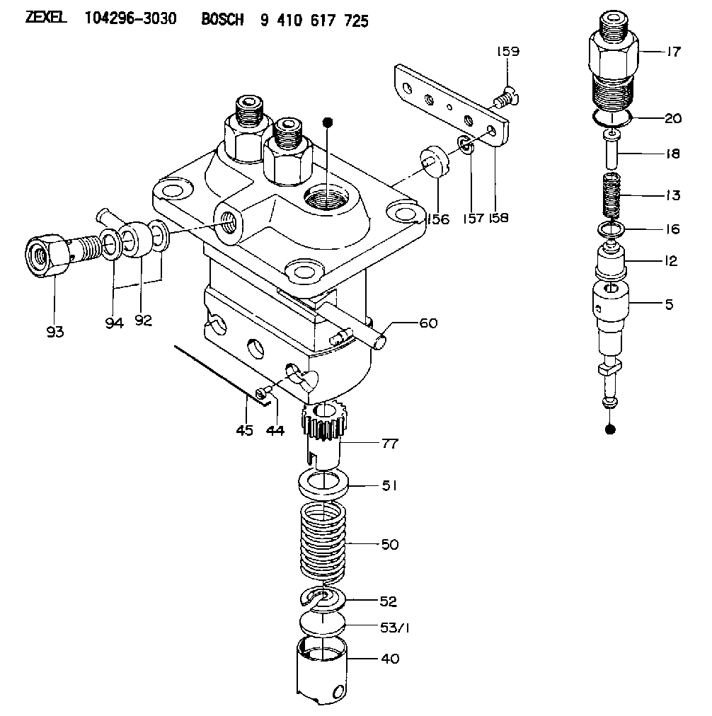
Information plunger-and-barrel assy
BOSCH
9 413 610 677
9413610677
ZEXEL
140154-2220
1401542220
ISHIKAWAJIMA-S
131116500
131116500

Rating:
Compare Prices: .
As an associate, we earn commssions on qualifying purchases through the links below

$81.00
25 Sep 2024
0.1102[0.05] pounds
CN: ChuChunWaiCe10
BDALEAOES Excavator Diesel Pump Plunger 140151-5720 K42 140154-2220 K221 140153-9020 K199, ChuChunWaiCe10
BDALEAOES * Good-quality materials: Our pump plunger is made of good-quality materials and precision machining, which can make the product durable and stable, operate smoothly and reduce noise and vibration. || * Precise technology: After fine processing and strict quality control, each pump plunger has high precision and can run better. || * Wide compatibility: Our product design is compatible with all kinds of car brands and models, so you can easily install and use it. || * Efficient and energy-saving: the plunger of automobile pump is designed with advanced technology, which provides efficient lubrication and energy-saving functions and prolongs the life of engine. || * Cold and hot adaptability: Our pump plunger performs well in both high and low temperature environments, which can make the engine work normally.
BDALEAOES * Good-quality materials: Our pump plunger is made of good-quality materials and precision machining, which can make the product durable and stable, operate smoothly and reduce noise and vibration. || * Precise technology: After fine processing and strict quality control, each pump plunger has high precision and can run better. || * Wide compatibility: Our product design is compatible with all kinds of car brands and models, so you can easily install and use it. || * Efficient and energy-saving: the plunger of automobile pump is designed with advanced technology, which provides efficient lubrication and energy-saving functions and prolongs the life of engine. || * Cold and hot adaptability: Our pump plunger performs well in both high and low temperature environments, which can make the engine work normally.

$61.49
28 Aug 2024
KR: Adabus
Excavator Diesel Pump Plunger 140151-5720 K42 140154-2220 K221 140153-9020 K199
Generic Placement on vehicle: Fuel injection pump || Country/region of manufacture: China || Material type: iron || Item weight: 0.2KG
Generic Placement on vehicle: Fuel injection pump || Country/region of manufacture: China || Material type: iron || Item weight: 0.2KG
Include in ###:
Cross reference number
Zexel num
Bosch num
Firm num
Name
140154-2220
131116500 ISHIKAWAJIMA-S
PLUNGER-AND-BARREL ASSY
C 26AA PLUNGER PL(PFR-Agriculture) PL
C 26AA PLUNGER PL(PFR-Agriculture) PL
Information:
Start By:a. remove valve covers Call out (1) and (2) are not used in this removal procedure. Call outs begin with number (3). 1. Remove bolts (3) that hold the valve cover bases to the cylinder head assembly. Remove valve cover bases (4).
To prevent damage to the fuel injection nozzle, hold adapter assembly (5) in position at the of injection nozzle (6) when fuel line nut (7) is loosened or tightened.
2. Use Tool (A) and a 7/8 5P0328 Crow Foot ( in) to loosen the fuel injection line nut at the nozzle end. 3. Use Tool (B) to loosen the nut at the fuel injection line adapter end. Remove inner fuel injection lines (8). Install caps and plugs on all fuel injection line openings to keep dirt out of the fuel system. 4. Remove bolts (9) that hold the rocker shaft assemblies to the cylinder head assembly.5. Remove rocker shaft assemblies (10). 6. Put identification marks on the push rods as to their location in the engine. Remove push rods (11). 7. Put identification marks on the bridges as to their location in the engine. Remove bridges (12) from the dowels on the cylinder head assembly.Install Rocker Shaft Assemblies & Push Rods
1. Put clean engine oil on the bridges and dowels. Install the original bridges in their respective locations. New bridges can be mixed.2. Install bridges (1) on the bridge dowels. While firmly pressing 0.5 to 4.5 kg (1 to 10 lb) straight down on the top contact surface of the bridge, turn the adjusting screw clockwise until contact is made with the valve stem. Turn the screw an additional 1/31/2 20 to 30 degrees ( to of 1 hex on nut). This will straighten the dowel in the guide and compensate for the slack in the threads. Hold the adjusting screw in this position and tighten the locknut to a torque of 30 4 N m (22 3 lb ft). Install the original push rods in their respective locations in the engine. New push rods can be mixed.3. Install push rods (2). 4. Put rocker shaft assemblies (3) in position on the cylinder head assembly.5. Put clean engine oil on the threads of the bolts that hold the rocker shaft assemblies in place. Tighten the bolts first to a torque of 270 25 N m (200 18 lb ft). Start with the bolt in the center of the rocker shaft assembly. Tighten the bolts again to a torque of 450 20 N m (330 15 lb ft). Tighten the bolts again by hand to a torque of 450 20 N m (330 15 lb ft).
Do not cause damage to the O-ring seals on the inner fuel lines.
6. Install inner fuel injection lines (4). Tighten the fuel injection line adapter nuts (5) to a torque 40 7 N m (30 5 lb ft) with Tool (A).
Do not let the tops of the fuel nozzles turn when the fuel