Information plunger-and-barrel assy
BOSCH
9 443 610 682
9443610682
ZEXEL
134152-1120
1341521120
ISUZU
1156320030
1156320030
Rating:
Include in ###:
Number on scheme 7/2

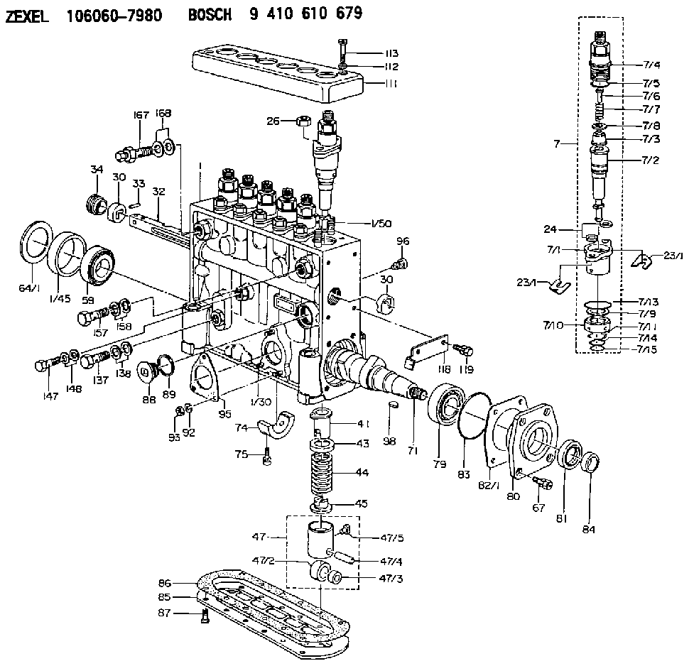
1060607980
as PLUNGER-AND-BARREL ASSY
P191
1060670680
as PLUNGER-AND-BARREL ASSY
1060671020
as PLUNGER-AND-BARREL ASSY
P191
Cross reference number
Zexel num
Bosch num
Firm num
Name
134152-1120
9 443 610 682
1156320030 ISUZU
PLUNGER-AND-BARREL ASSY
C 14EU PLUNGER ASSY PL(P) PL
C 14EU PLUNGER ASSY PL(P) PL
134152-1120
9 443 610 682
ME741405 MITSUBISHI
PLUNGER-AND-BARREL ASSY
C 14EU PLUNGER ASSY PL(P) PL
C 14EU PLUNGER ASSY PL(P) PL
Information:
Illustration 1 g00563639
Schematic of the RTD module
Illustration 2 g00563641
Schematic of the RTD
Illustration 3 g00562911
Schematic of the RTDFunctional Test
Check the electrical connectors and check the wiring.
Bodily contact with electrical potential can cause bodily injury or death.To avoid the possibility of injury or death, ensure that the main power supply has been disconnected before performing any maintenance or removing any modules.
Disconnect the power supply.
Check the electrical connectors and check the wiring for damage or bad connections.
Verify that all modules are properly seated.
Verify the status of the LED on the SLC 5/04.The results of the preceding procedure are in the following list:
All of the components are fully installed. All of the components are free of corrosion. All of the components are free of damage. All of the modules are properly seated. Proceed to 2.
The components are not fully installed. The components are not free of corrosion. The components are damaged. All of the modules are not properly seated. Repair the component. Verify that the repair resolves the problem. STOP.
Check the RTD.
Bodily contact with electrical potential can cause bodily injury or death.To avoid the possibility of injury or death, ensure that the main power supply has been disconnected before performing any maintenance or removing any modules.
Disconnect the RTD from the wiring harness. This is done by removing the RTD connector head.
Measure the resistance on the sensor. Measure the resistance between the following terminals: Terminal 1 and Terminal 2.
Use table 1 in order to determine if the RTD is functioning normally.
Table 1
RTD
Temperature and Resistance
Temperature Ohms Difference per °C
0 °C (32 °F) 100.00 0.39
10 °C (50.0 °F) 103.90 0.39
20 °C (68 °F) 107.79 0.39
30 °C (86 °F) 111.67 0.39
40 °C (104 °F) 115.54 0.39
50 °C (122 °F) 119.40 0.39
60 °C (140 °F) 123.24 0.38
70 °C (158 °F) 127.07 0.38
80 °C (176 °F) 130.89 0.38
90 °C (194 °F) 134.70 0.38
100 °C (212 °F) 138.50 0.38
110 °C (230 °F) 142.29 0.38
120 °C (248 °F) 146.06 0.38
130 °C (266 °F) 149.82 0.37
140 °C (284 °F) 153.58 0.37
150 °C (302 °F) 157.31 0.37 The results of the preceding procedure are in the following list:
The resistance is correct. The RTD is functioning normally. Proceed to 3.
The resistance is not correct. The RTD is not functioning normally. Replace the RTD. Stop.
Measure the resistance of the interconnect wiring harness.
Connect the RTD to the wiring harness. This is done by connecting the RTD connector head.
Locate the RTD terminal and locate the sense terminal. The terminals are located in the MECP. The RTD terminal is terminal 2 and the sense terminal is terminal 3.Reference: Schematic, RENR2458, "3600 Diesel Marine Monitoring System Electrical System".
Measure the resistance on the
Have questions with 134152-1120?
Group cross 134152-1120 ZEXEL
Isuzu
134152-1120
9 443 610 682
1156320030
PLUNGER-AND-BARREL ASSY
Mitsubishi
134152-1120
9 443 610 682
ME741405
PLUNGER-AND-BARREL ASSY