Information plunger-and-barrel a
BOSCH
9 413 610 102
9413610102
ZEXEL
131151-5820
1311515820
Rating:
Compare Prices: .
As an associate, we earn commssions on qualifying purchases through the links below

$259.36
14 Nov 2024
KR: Adabus
Diesel Fuel Pump A74 Plunger Element 131151-5820
Generic
Generic

$42.98
11 Jul 2024
CN: Diesel Injection Par
Cabezales 6Pcs Diesel Injection Pump Plunger Barrel Element 131151-5820 A74 Fit for KOMATSU S4D105 S6D105 SL6D105 6D105
Cabezales Manufacturer MFR Number:131151-5820 / 9413610102 Stamping No.: A74 || Package: 6 pieces of plunger and barrel.Neutral packing. || Application:Fit for KOMATSU S4D105 S6D105 SL6D105 6D105 . || Premium Quality:Our plungers and barrels made of premium strength metal and composite plastic.we have a good air and fuel mixing ability and excellent ability of fuel pump systems,and plunger assembly be inspected reliability in the factory. || Notice:Please you carefully check your vehicle plunger barrel and make sure that the number must be completely the same as our description fitment,if you have any problem,please you contact us by email,we will have professional customer service within 24 hours.
Cabezales Manufacturer MFR Number:131151-5820 / 9413610102 Stamping No.: A74 || Package: 6 pieces of plunger and barrel.Neutral packing. || Application:Fit for KOMATSU S4D105 S6D105 SL6D105 6D105 . || Premium Quality:Our plungers and barrels made of premium strength metal and composite plastic.we have a good air and fuel mixing ability and excellent ability of fuel pump systems,and plunger assembly be inspected reliability in the factory. || Notice:Please you carefully check your vehicle plunger barrel and make sure that the number must be completely the same as our description fitment,if you have any problem,please you contact us by email,we will have professional customer service within 24 hours.

$72.00
17 Sep 2024
0.1102[0.05] pounds
CN: ChuChunWaiCe10
131151-5820 Pump Plunger A74
BDALEAOES * Good-quality materials: Our pump plunger is made of good-quality materials and precision machining, which can make the product durable and stable, operate smoothly and reduce noise and vibration. || * Precise technology: After fine processing and strict quality control, each pump plunger has high precision and can run better. || * Wide compatibility: Our product design is compatible with all kinds of car brands and models, so you can easily install and use it. || * Efficient and energy-saving: the plunger of automobile pump is designed with advanced technology, which provides efficient lubrication and energy-saving functions and prolongs the life of engine. || * Cold and hot adaptability: Our pump plunger performs well in both high and low temperature environments, which can make the engine work normally.
BDALEAOES * Good-quality materials: Our pump plunger is made of good-quality materials and precision machining, which can make the product durable and stable, operate smoothly and reduce noise and vibration. || * Precise technology: After fine processing and strict quality control, each pump plunger has high precision and can run better. || * Wide compatibility: Our product design is compatible with all kinds of car brands and models, so you can easily install and use it. || * Efficient and energy-saving: the plunger of automobile pump is designed with advanced technology, which provides efficient lubrication and energy-saving functions and prolongs the life of engine. || * Cold and hot adaptability: Our pump plunger performs well in both high and low temperature environments, which can make the engine work normally.
Include in ###:
Number on scheme 30

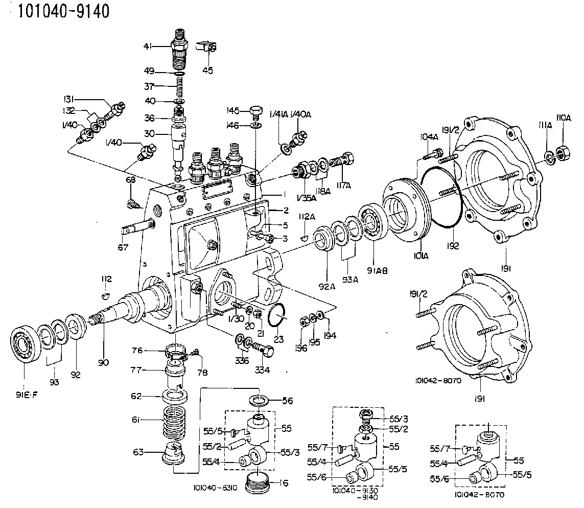
1010409140
as PLUNGER-AND-BARREL ASSY
A74
1010600800
as PLUNGER-AND-BARREL ASSY
1010600880
as PLUNGER-AND-BARREL ASSY
A74
1010602470
as PLUNGER-AND-BARREL ASSY
1010604570
as PLUNGER-AND-BARREL ASSY
A74
1010604800
as PLUNGER-AND-BARREL ASSY
Cross reference number
Zexel num
Bosch num
Firm num
Name
Information:
2. Turn the crankshaft until two of the pistons are at bottom center. Remove the nuts and bolts (1) from the connecting rods that are at bottom center. Remove connecting rod caps (2). Put identification marks on them for installation purposes.
Do not let the connecting rods hit the crankshaft or the bottom edge of the cylinder liners when the pistons are removed.
3. Push the connecting rods and pistons away from the crankshaft until the piston rings are out of the cylinder liners. Remove the two pistons from the engine.4. Keep each connecting rod cap with its respective connecting rod and piston. Put identification marks on each piston as to its location in the engine.5. Do Steps 1 through 4 for the removal of the remaining pistons.Install Pistons & Connecting Rods
1. Turn the crankshaft until the bearing journals for the pistons to be installed are at bottom center.2. Put clean engine oil on the crankshaft journals and on the inside of the cylinder liners. Put clean engine oil on the piston rings and the connecting rod bearings.3. Move the piston rings on the pistons until the ring openings are approximately 90° apart. 4. Put the piston in the cylinder liner with the "V" mark on the piston in alignment with the "V" mark on the cylinder block. Put Tool (A) in position on the cylinder block and compress the piston rings.5. Push the piston into the cylinder liner and out of the ring compressor. 6. Pull the connecting rod into position on the crankshaft as shown. Install connecting rod bolts (1) in the connecting rods.7. Put clean engine oil on the lower half of the connecting rod bearing. Put 2P2506 Thread Lubricant on the bolt threads and on the surfaces of the nuts that make contact with the connecting rod caps.
When the connecting rod caps are installed, make sure the number on the side of the cap is next to and respective with the number on the side of the connecting rod.
8. Install connecting rod caps (2) and the nuts that hold them. Tighten the nuts to a torque of 40 4 N m (30 3 lb ft). Put a mark on each nut as to its location. Tighten them 90° 5° more.9. Do Steps 1 through 8 for the remainder of the pistons.End By:a. install oil pumpb. install oil pan platec. install cylinder head assembly and spacer plateDisassemble Pistons & Connecting Rods
Start By:a. remove pistons and connecting rods 1. Remove the rings from the pistons with Tool (A). 2. Remove retaining ring (3), piston pin (1) and connecting rod (2) from the piston.3. Remove the bearings from the crankshaft end of the connecting rod.4. See Use Of Piston Pin Bearing Removal And Installation Tools, Special Instructions, Form No. SMHS7295-02 for more information about removal and installation of piston pin bearings. Be sure to remove the bearings from the crankshaft end of connecting rod.5. Heat the connecting rod in an oven to a temperature of 176