Information plunger-and-barrel assy
BOSCH
9 413 610 059
9413610059
ZEXEL
130101-1320
1301011320
ISUZU
5156320040
5156320040
Rating:
Compare Prices: .
As an associate, we earn commssions on qualifying purchases through the links below

Fuel Injector Pump Element Diesel Plunger 105990-51100 E8 130101-1320 K65 131102-0020 A15 131151-0120 A17 131151-1220 A28 - (Color: 131151-0120 A17)
Generic Color: 131151-0120 A17
Generic Color: 131151-0120 A17
$37.59
07 Dec 2024
VN: Laminee
Fuel Injector Pump Element Diesel Plunger 105990-51100 E8 130101-1320 K65 131102-0020 A15 131151-0120 A17 131151-1220 A28 - (Color: 130101-1320 K65)
Generic Color: 130101-1320 K65
Generic Color: 130101-1320 K65
Include in ###:
Number on scheme 30

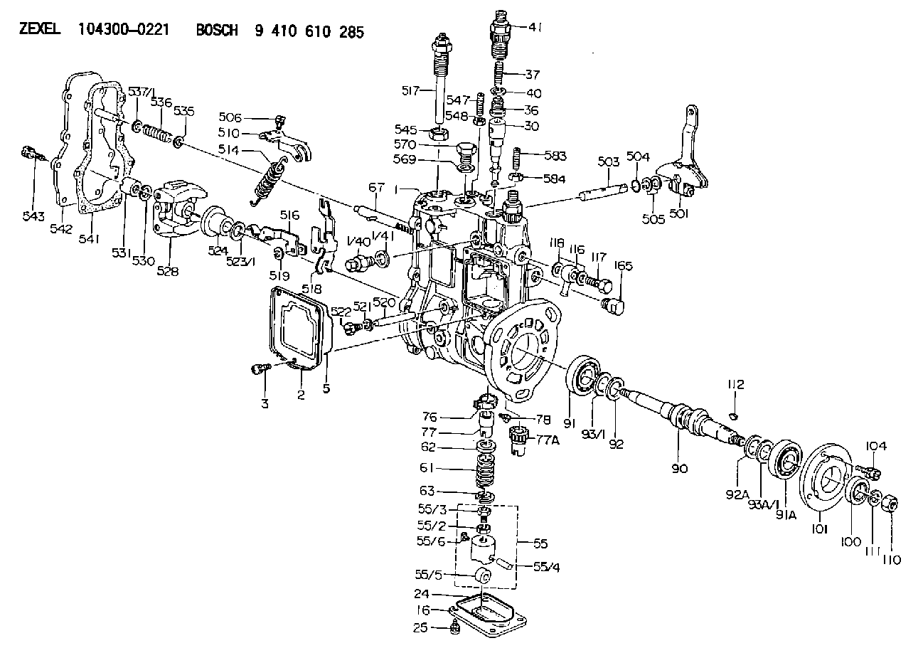
1043000221
as PLUNGER-AND-BARREL ASSY
1043000281
as PLUNGER-AND-BARREL ASSY
K65
1043000291
as PLUNGER-AND-BARREL ASSY
1043000301
as PLUNGER-AND-BARREL ASSY
K65
1043000321
as PLUNGER-AND-BARREL ASSY
1043000361
as PLUNGER-AND-BARREL ASSY
K65
1043000511
as PLUNGER-AND-BARREL ASSY
1043003250
as PLUNGER-AND-BARREL ASSY
K65
1043003890
as PLUNGER-AND-BARREL ASSY
1043004092
as PLUNGER-AND-BARREL ASSY
K65
1043004120
as PLUNGER-AND-BARREL ASSY
1043004121
as PLUNGER-AND-BARREL ASSY
K65
1043004390
as PLUNGER-AND-BARREL ASSY
Cross reference number
Information:
start by:a) remove exhaust manifoldb) remove air inlet manifoldc) remove valve coversd) remove fuel injection linese) remove fuel injection nozzles1. Remove the coolant from the cooling system. 2. Remove clamp (2) from water sleeves (1) in each cylinder head. Push the water sleeves into the timing gear cover with tool (A) and a screwdriver. 3. Remove bolt (3) from the bracket on the dipstick tube. 4. Remove bolts (4) and stud (5) from the heads.
Make sure the fuel injection nozzles are removed before the cylinder heads are removed. The fuel injection nozzles go through the cylinder heads and the nozzle tips can be broken off if the nozzles are not removed from the heads.
5. Install tooling (B) and fasten a hoist. Remove bolts (7), cylinder head (6) and the gasket. The weight of the cylinder head is 54 kg (120 lb.).Install Cylinder Heads
1. Clean the contact surfaces of the cylinder head and cylinder block. Make sure the surfaces are clean and dry. Install a new cylinder head gasket. Clean the bore in the cylinder head for the water sleeves. Put oil on the seals on the water sleeves.2. Install tooling (B) in the cylinder head. Fasten a hoist and put the cylinder head in position on the cylinder block.3. Put 6V4876 Molykote Lubricant on the bolt threads and install the bolts that hold the cylinder head in their correct location. Tighten the bolts in the cylinder head according to the HEAD BOLT TORQUE CHART.
The higher cylinder head bolt torque may be used on earlier engines ONLY if the bolts are replaced with the later higher strength bolts (seven dash marks on the bolt head). If the earlier bolts are tightened to the later torque specification, they may yield (stretch) and lose their clamping force.
4. Install water sleeve into cylinder head with tool (A). Install the clamp on the water sleeves.5. Fill the cooling system with coolant to the correct level. end by:a) install fuel injection nozzlesb) install rocker shafts and push rodsc) install valve coversd) install air inlet manifolde) install exhaust manifold
Illustration 1. Bolt head identification.Disassemble Cylinder Heads
start by: a) remove cylinder heads1. Fasten a hoist and put the cylinder head in position on tool (A). Use adapter plates (1) from tooling (A) to hold the head in place. 2. Put the valve springs under compression with tool (C). 3. Remove the locks from the valves. Earlier engines have an inner valve spring. Later engines have only one valve spring and a spacer instead of inner spring.4. Remove tool (C), retainer, spring, washer and valve from the cylinder head. Put identification on the valve as to its location in the cylinder head. 5. Check the valve spring force with tool (B). For the correct spring force, see the subject VALVES in SPECIFICATIONS.6. Do Steps 2 through 5 for the remainder of the valves.7. Remove the valve seat inserts with tooling (D). The valve guides are part of the cylinder head. Measure the bore in each valve guide 19.0