Information plate
BOSCH
9 423 617 230
9423617230
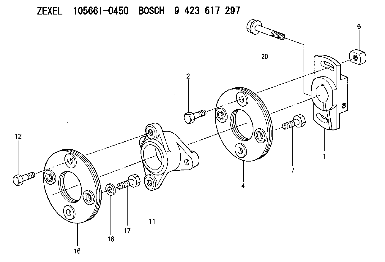
ZEXEL
156605-4620
1566054620
ISUZU
1157890910
1157890910
Rating:
Compare Prices: .
As an associate, we earn commssions on qualifying purchases through the links below

$53.12
11 Dec 2023
LV: Gear245
Bosch 9423617230 Clamping Jaw
BOSCH
BOSCH
Include in ###:
Cross reference number
Zexel num
Bosch num
Firm num
Name
156605-4620
9 423 617 230
1157890910 ISUZU
PLATE
C 14GU PLATE COUP
C 14GU PLATE COUP
156605-4620
9 423 617 230
1683399013 NISSAN-DIESEL
PLATE
C 14GU PLATE COUP
C 14GU PLATE COUP
Information:
Start By:a. remove fuel injection nozzlesb. remove cylinder head assembly and spacer plate 1. Put compression on valve spring (2) with Tool (A). Remove locks (1).2. Remove Tool (A), rotocoil, spring, valve stem oil shield and valve. Put identification marks on valves with respect to their location in the cylinder head. 3. Check the spring force with Tool (B). The spring force is 257 25 N (57.8 5.6 lb). The length of spring under test force is 44.86 mm (1.766 in). The free length after test is 52.07 mm (2.050 in).4. Do Steps 1 through 3 again for the remainder of the valves.Install Valves
1. Put clean engine oil on the valve stems. Install valve (3), oil shield (4), spring (2) and rotocoil (1) in the cylinder head. 2. Put Tool (A) in position on the valve spring. Install the locks with Tool (B).
Locks can be thrown from valve when the compressor is released if they are not in their correct position on valve stem. Personal injury can be the result if not carefully removed.
3. Remove Tool (A), and hit the top of valve with a plastic hammer to be sure the locks are in their correct position on valve.4. Do Steps 1 through 3 again for the remainder of the valves.End By:a. install cylinder head assembly and spacer plateb. install fuel injection nozzles
Have questions with 156605-4620?
Group cross 156605-4620 ZEXEL
Isuzu
156605-4620
9 423 617 230
1157890910
PLATE
Nissan-Diesel
156605-4620
9 423 617 230
1683399013
PLATE