Information plate
BOSCH
9 423 617 080
9423617080
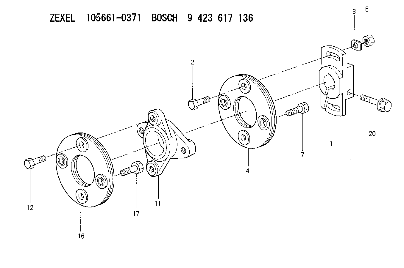
ZEXEL
156605-2320
1566052320
ISUZU
1157890650
1157890650
Rating:
Compare Prices: .
As an associate, we earn commssions on qualifying purchases through the links below

Include in ###:
Cross reference number
Zexel num
Bosch num
Firm num
Name
156605-2320
9 423 617 080
1157890650 ISUZU
PLATE
C 14GU PLATE COUP
C 14GU PLATE COUP
156605-2320
9 423 617 080
226011220A HINO
PLATE
C 14GU PLATE COUP
C 14GU PLATE COUP
156605-2320
9 423 617 080
16833Z9000 NISSAN-DIESEL
PLATE
C 14GU PLATE COUP
C 14GU PLATE COUP
Information:
2. Loosen two hose clamps (1).3. Remove hose (2). 4. Remove two bolts (3).5. Remove elbow (5).6. Remove fumes disposal tube (4) for access to the water pump.7. Disconnect coolant conditioner hose (6).8. Remove heater hose (12) (previously removed).9. Loosen hose clamp (15).10. Disconnect lower radiator hose (13).11. Remove two bolts (14) from oil cooler. Check gasket for wear or damage. Replace if necessary.12. Remove four bolts (10).13. Remove water pump cover (11).14. Remove seven long bolts (7).15. Reposition air conditioning lines and oil line (8) after bolts are removed.16. Remove water pump (9). Check seals and O-rings for wear and damage before installation, replace as necessary. For installation of the water pump, reverse the removal steps.17. Fill the cooling system with coolant to correct level. See the Operation & Maintenance Manual.Disassemble Water Pump
*Part of 1P510 Driver Group.Start By:a. remove water pump The water pump seal can be replaced without removing the water pump from the engine. An intermittent leakage of a small amount of coolant from the hole in the water pump housing is not an indication of a water pump seal failure. This is required to provide lubrication for the seal. Replace the water pump seal only if a large amount of leakage or a constant flow of coolant is observed draining from the water pump housing.1. Remove O-ring seal (1) from the adapter.2. Remove adapter (2) from the housing. Remove the O-ring seal from the outside diameter of the adapter.3. Remove bolt (3) and the retainer that hold the impeller on the shaft. 4. Use Tool (A) to remove impeller (4) from the shaft. 5. Remove the spring and seal (5) from the shaft. 6. Remove four bolts (7) from retainer (6) that hold the shaft assembly to the pump housing.7. Remove O-ring seal (8) from the housing. 8. Remove gear and shaft assembly (10) from the housing.9. Remove bolt (9) and the retainer from the shaft assembly. 10. Use a press to remove the shaft assembly from gear (11). Remove the retainer from the shaft assembly. 11. Remove bearing (13), spacer (14) and bearing (12) from the shaft. 12. Remove lip-type seal (15) from the housing.13. Turn the housing over, and remove ceramic ring (16) and the seal.Assemble Water Pump
1. Use 6V1541 Quick Cure Primer to clean shaft (8) and the seal counterbore in the pump housing.2. Install bearing (4), spacer (3) and bearing (2) on shaft (8).3. Put retainer (1) and gear (7) in position on the shaft assembly. Install retainer (6) and bolt (5). 4. Use Tool (A) to install the lip-type seal in the housing as shown. Put a small amount of clean SAE 30 Oil on the lip of the seal. 5. Install a new O-ring seal (10) on the housing.6. Put shaft assembly (9) in position in the housing. Install the bolts that hold the retainer to the housing.
Clean water only is permitted for use as a lubricant for assistance at installation. Do not damage or put hands on
Have questions with 156605-2320?
Group cross 156605-2320 ZEXEL
Isuzu
156605-2320
9 423 617 080
1157890650
PLATE
Hino
156605-2320
9 423 617 080
226011220A
PLATE
Nissan-Diesel
156605-2320
9 423 617 080
16833Z9000
PLATE