Information plate
BOSCH
9 423 617 079
9423617079
ZEXEL
156605-1620
1566051620
ISUZU
9813850240
9813850240
Rating:
Compare Prices: .
As an associate, we earn commssions on qualifying purchases through the links below

$56.00
18 May 2021
US: US AUTO PARTS EXPERT
Washer Thrust, Side Gear 9-81385-024-0
Isuzu Other Part Number:UAP-104-032 || Fitment Type:Direct Replacement || Country/Region of Manufacture:Japan
Isuzu Other Part Number:UAP-104-032 || Fitment Type:Direct Replacement || Country/Region of Manufacture:Japan
Include in ###:
Cross reference number
Zexel num
Bosch num
Firm num
Name
156605-1620
9 423 617 079
9813850240 ISUZU
PLATE
C 14GU PLATE COUP
C 14GU PLATE COUP
156605-1620
9 423 617 079
6073160380 HINO
PLATE
C 14GU PLATE COUP
C 14GU PLATE COUP
156605-1620
9 423 617 079
226011160A HINO
PLATE
A C 14GU PLATE COUP
A C 14GU PLATE COUP
156605-1620
9 423 617 079
16833Z9001 NISSAN-DIESEL
PLATE
C 14GU PLATE COUP
C 14GU PLATE COUP
Information:
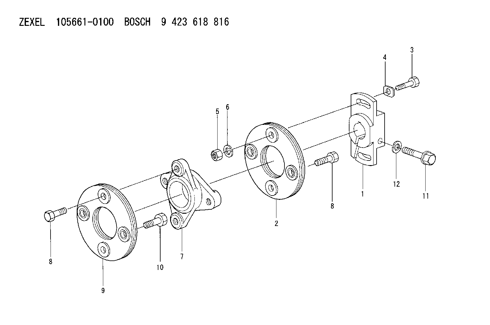
1. Remove nuts (1), cover (2), and the gasket. 2. Put No. 1 piston at the top center compression position (TC) with the following procedure:a. Remove plug (3), two bolts and cover (2) from the flywheel housing. b. Install Tool (B) in the flywheel housing. Use Tool (B) to slowly rotate the engine in the direction of normal rotation, (counterclockwise as seen from the flywheel end of the engine), until timing bolt (4) can be installed in the flywheel housing and into the hole in the flywheel. c. Remove the valve cover from the valve cover base. Check to see if both rocker arms (5) for the No. 1 cylinder can be moved backward and forward. The No. 1 piston is at the top center compression position (TC) when the timing bolt is installed in the flywheel and both rocker arms for the No. 1 cylinder can be moved backward and forward. If both rocker arms cannot be moved, the No. 1 piston is not at the top center compression position (TC). Remove the timing bolt from the flywheel and rotate the engine in the direction for normal rotation, (counterclockwise as seen from the flywheel end of the engine one full turn 360 degrees, and install the timing bolt again.3. Remove the timing bolt, and use Tool (B) to rotate the engine in the opposite direction of normal rotation (clockwise as seen from the flywheel end of the engine) a minimum of 30 degrees. The timing is correct if Tool (A) and the timing bolt can be installed at the same time. The timing procedure in the Testing & Adjustment Manual must be done again if the timing bolt and Tool (A) can not be installed at the same time.4. Remove the plug from the timing pin hole in the fuel injection pump housing. Install Tool (A) in the timing pin hole. 5. Remove eight bolts (6) and automatic timing advance (7). 6. Remove gear (9) from fuel injection pump camshaft (8).The following steps are for the installation procedure.7. Install gear (9) on fuel injection pump camshaft (8). 8. Install two 3/8 in 16 NC x 6 in (152.4 mm) long guide bolts (10). Space the guide bolts evenly.
There is a light spring located beneath the flyweight cover (12). Hold cover (12) while removing last nut (11). Slowly remove flyweight cover (12) to avoid dropping the spring.
9. Remove four nuts (11) and remove flyweight cover (12). 10. Put automatic timing advance (13) in position on the fuel injection pump camshaft, and install four bolts (14). Tighten bolts (14) just past finger tight. Remove guide bolts (15). 11. Install four nuts (16). Install Tool (C). 12. Tighten four knurled nuts (17) finger tight.
Do not use any tools to tighten the knurled nuts.
13. Install all mounting bolts (14) and tighten to 55 10 N m (41 7 lb ft).14. Loosen knurled nuts (17). Remove four nuts (16) and remove Tool (C).15. Install the spring and flyweight cover
Have questions with 156605-1620?
Group cross 156605-1620 ZEXEL
Isuzu
156605-1620
9 423 617 079
9813850240
PLATE
Hino
156605-1620
9 423 617 079
6073160380
PLATE
156605-1620
9 423 617 079
226011160A
PLATE
Nissan-Diesel
156605-1620
9 423 617 079
16833Z9001
PLATE