Information plate
BOSCH
9 423 617 073
9423617073
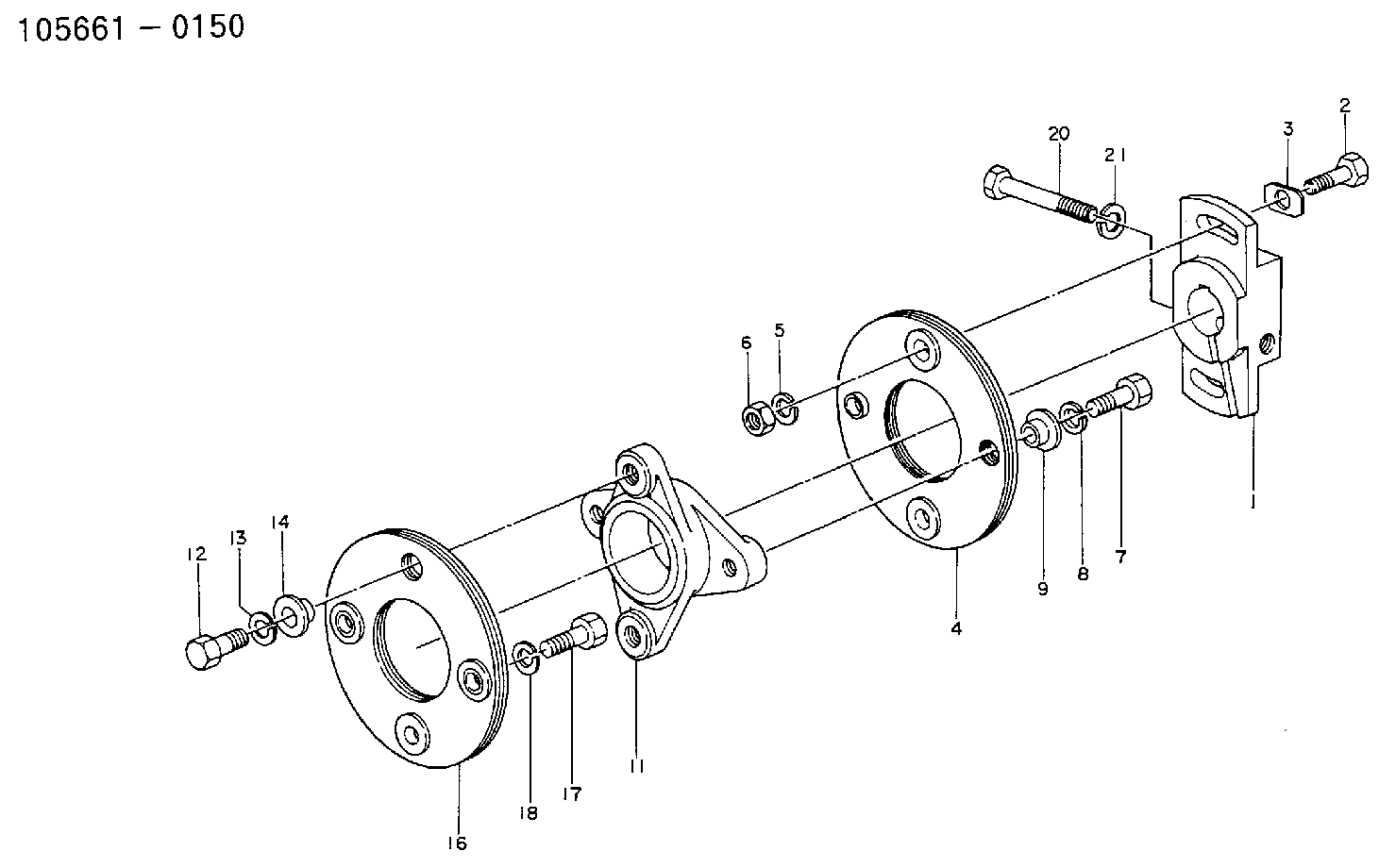
ZEXEL
156605-1120
1566051120
ISUZU
9813811160
9813811160

Rating:
Compare Prices: .
As an associate, we earn commssions on qualifying purchases through the links below

$172.40
01 Jul 2021
US: # 1 Quality Parts
PLATE FOR ALLIS-CHALMERS: 156605-1120
Parts Express ALLIS-CHALMERS || All Brand new & rebuilt items comes with 1 year warranty. || PLATE. Category: ALLIS-CHALMERS FORKLIFT PARTS. This part can also be found under the following part numbers: ACDK156605-1120 156605-1120 ALLIS CHALMERS/TUSK AC DK156605-1120 ALLIS CHALMERS/TUSKDK156605-1120 ACDK1566051120 AC DK1566051120 Â DK156605-1120 ALLIS CHALMERS/TUSK DK1566051120 ALLIS CHALMERS/TUSKDK1566051120 Â DK1566051120. All Brand new & rebuilt items comes with 1 year warranty.
Parts Express ALLIS-CHALMERS || All Brand new & rebuilt items comes with 1 year warranty. || PLATE. Category: ALLIS-CHALMERS FORKLIFT PARTS. This part can also be found under the following part numbers: ACDK156605-1120 156605-1120 ALLIS CHALMERS/TUSK AC DK156605-1120 ALLIS CHALMERS/TUSKDK156605-1120 ACDK1566051120 AC DK1566051120 Â DK156605-1120 ALLIS CHALMERS/TUSK DK1566051120 ALLIS CHALMERS/TUSKDK1566051120 Â DK1566051120. All Brand new & rebuilt items comes with 1 year warranty.
$206.03
01 Jul 2021
US: EFI Equipment and Pa
PLATE FOR ALLIS-CHALMERS: 156605-1120
Parts Express ALLIS-CHALMERS || All Brand new & rebuilt items comes with 1 year warranty. || PLATE. Category: ALLIS-CHALMERS FORKLIFT PARTS. This part can also be found under the following part numbers: ACDK156605-1120 156605-1120 ALLIS CHALMERS/TUSK AC DK156605-1120 ALLIS CHALMERS/TUSKDK156605-1120 ACDK1566051120 AC DK1566051120 Â DK156605-1120 ALLIS CHALMERS/TUSK DK1566051120 ALLIS CHALMERS/TUSKDK1566051120 Â DK1566051120. All Brand new & rebuilt items comes with 1 year warranty.
Parts Express ALLIS-CHALMERS || All Brand new & rebuilt items comes with 1 year warranty. || PLATE. Category: ALLIS-CHALMERS FORKLIFT PARTS. This part can also be found under the following part numbers: ACDK156605-1120 156605-1120 ALLIS CHALMERS/TUSK AC DK156605-1120 ALLIS CHALMERS/TUSKDK156605-1120 ACDK1566051120 AC DK1566051120 Â DK156605-1120 ALLIS CHALMERS/TUSK DK1566051120 ALLIS CHALMERS/TUSKDK1566051120 Â DK1566051120. All Brand new & rebuilt items comes with 1 year warranty.
Include in ###:
Cross reference number
Zexel num
Bosch num
Firm num
Name
156605-1120
9 423 617 073
9813811160 ISUZU
PLATE
C 14GU PLATE COUP
C 14GU PLATE COUP
156605-1120
9 423 617 073
6073160500 HINO
PLATE
C 14GU PLATE COUP
C 14GU PLATE COUP
156605-1120
9 423 617 073
226011170A HINO
PLATE
A C 14GU PLATE COUP
A C 14GU PLATE COUP
156605-1120
9 423 617 073
ME722165 MITSUBISHI
PLATE
C 14GU PLATE COUP
C 14GU PLATE COUP
156605-1120
9 423 617 073
1683390000 NISSAN-DIESEL
PLATE
C 14GU PLATE COUP
C 14GU PLATE COUP
Information:
Introduction
This Special Instruction provides detailed instructions on the installation of the sleeve into the compensator group of the 3408E and 3412E Unit Injector Hydraulic Pump. If leaks are experienced at the joint of the compensator and the adapter block, the 174-8943 Sleeve may be installed to improve sealing. The new press fit sleeve contains the O-ring more securely than the original slip fit sleeve.Note: Engines built prior to the serial number break that contain the new sleeve have a "S" stamped at the end of the part number on the serial number plate of the pump. The reworked part numbers appear as "144-0835-06S". Individual Components
Table 1
Quantity Part Number Part Description
1 174-8943 Sleeve
1 135-2652 O-Ring
1 033-6039 O-Ring
6 9X-7680 O-Ring Necessary Tools
One of the following tools may be used to insert the new sleeve into the compensator group.
A 31.750 mm (1.250 inch) diameter flat plate.
The 1P-0467 Drive Plate from 1P-0510 Driver Group .
An acceptable bearing insertion tool.Removal Of The O-Ring Seals
Illustration 1 g00638376
Remove the four bolts (1) from the compensator (2). Remove the compensator and the adapter. Do not adjust the compensator. Refer to Special Instruction, REHS0192-03, step 3 of procedure for "Disassembly of the 144-0835 Unit Injector Hydraulic Pump Group ".
Illustration 2 g00638368
Remove the four O-ring seals (3) from the bottom side of the adapter. Refer to Special Instruction, REHS0192-03, step 4 of procedure for "Disassembly of the 144-0835 Unit Injector Hydraulic Pump Group ".
Illustration 3 g00638372
Remove the four O-ring seals (4) from the two housings. Refer to Special Instruction, REHS0192-03, step 5 of procedure for "Disassembly of the 144-0835 Unit Injector Hydraulic Pump Group ".
Remove the slip fit sleeve from the compensator housing.Installation Of The Sleeve
Illustration 4 g00637918
(1) Compensator assembly. (2) 174-8943 Sleeve .
Invert the compensator assembly (1). Hold the compensator assembly securely within a vise or a press table.
Start the sleeve (2) by hand into the compensator assembly (1) .Note: It is important that the groove on the outside diameter of the sleeve is oriented toward the O-ring in the joint. If this is not done, there will not be sufficient room to properly seal the O-ring.
Press the sleeve (2) flush with the surface of the compensator assembly (1) using the 1P-0467 Drive Plate or by using an acceptable bearing insertion tool.Installation Of The O-Ring Seals
Illustration 5 g00638368
Install the four O-ring seals (3) on the bottom side of the adapter. Refer to Special Instruction, REHS0192-03, step 16 of procedure for "Assembly of the 144-0835 Unit Injector Hydraulic Pump Group ".
Illustration 6 g00638372
Install the four O-rings (4) on the two housings. Refer to Special Instruction, REHS0192-03, step 17 of procedure for "Assembly of the 144-0835 Unit Injector Hydraulic Pump Group ".
Illustration 7 g00638376
Install the compensator assembly (2) and the adapter as a unit vertically so that the O-rings seals are not damaged. Tighten the four bolts (1) to the following torque.Torque for bolts ... 8 1 N
Have questions with 156605-1120?
Group cross 156605-1120 ZEXEL
Isuzu
156605-1120
9 423 617 073
9813811160
PLATE
Hino
156605-1120
9 423 617 073
6073160500
PLATE
156605-1120
9 423 617 073
226011170A
PLATE
Mitsubishi
156605-1120
9 423 617 073
ME722165
PLATE
Nissan-Diesel
156605-1120
9 423 617 073
1683390000
PLATE