Information plate
BOSCH
9 411 619 588
9411619588
ZEXEL
140296-1700
1402961700
Rating:
Include in ###:
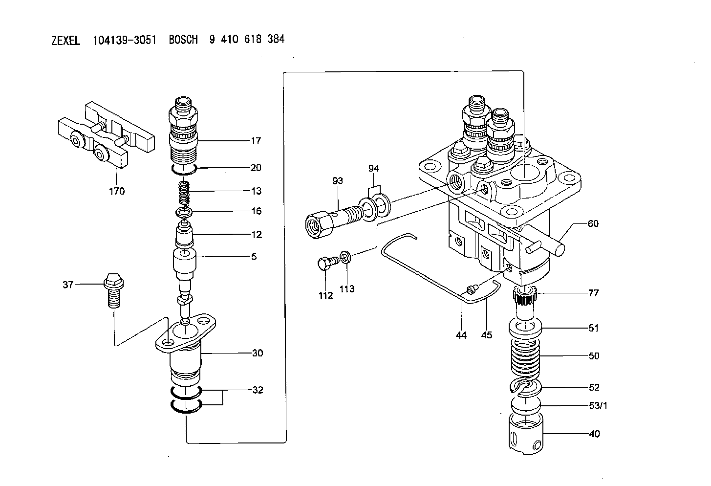
Number on scheme 53/1

1041393051
as PLATE
1041393070
as PLATE
D19T3.475
1041394141
as PLATE
1041394180
as PLATE
D19T3.475
Cross reference number
Zexel num
Bosch num
Firm num
Name
140296-1700
9 411 619 588
PLATE
C 23XX PLATE PFR- parts PFR
C 23XX PLATE PFR- parts PFR
Information:
2. Remove bolts (1). 3. Disconnect air hose (2) from the cylinder head to the air compressor.4. Remove air compressor inlet tube (3).5. Disconnect the air tube from the inlet manifold to the fuel ratio control. 6. Remove oil inlet tube (4).7. Remove two bolts (5). 8. Remove the bolts that hold the cylinder head to the cylinder block.9. Fasten a hoist to the cylinder head. Carefully remove the head from the block. Weight is 164 lb. (74.4 kg).Install Cylinder Head
1. Install a new, dry cylinder head gasket.2. Fasten a hoist to the cylinder head and put the cylinder head in position on the cylinder block.3. Install the push rods. Put the rocker shaft in position on the engine.
Dowel pins (A) on each end of the rocker shaft assembly must be in alignment with holes (B). If the pins and holes are not in alignment during installation of the rocker shaft assembly, damage to the rocker shaft assembly will be the result.
4. Put 5P3931 Anti-Seize Compound on the threads of cylinder head and rocker shaft bolts. Install the bolts in the following step sequence: 1. Tighten all bolts in number sequence to a torque of 115 lb. ft. (155 N m).2. Tighten all bolts in number sequence to a torque of 185 13 lb. ft. (250 17 N m).3. Tighten all bolts in number sequence (hand turn only) to a torque of 185 13 lb. ft. (250 17 N m) again.4. Tighten all bolts (hand turn only) in letter sequence to a torque of 32 5 lb. ft. (43 7 N m). 5. Make an adjustment to the valves to get a clearance of .015 in. (0.38 mm) for the intake valves and .025 in. (0.64 mm) for the exhaust valves.6. Install the turbocharger oil inlet tube. Install the two bolts that connect the oil outlet tube to the turbocharger.7. Connect the air tube from the fuel ratio control to the inlet manifold.8. Connect the air hose from the air compressor to the cylinder head.9. Install the two bolts removed from the temperature regulator.10. Fill the cooling system with coolant to the correct level.end by:a) install fan driveb) install fuel injection lines
Have questions with 140296-1700?
Group cross 140296-1700 ZEXEL
140296-1700
9 411 619 588
PLATE