Information plate
BOSCH
9 442 610 161
9442610161
ZEXEL
029998-0010
0299980010
ISUZU
8944281600
8944281600
Rating:
Include in #2:
104760-2150
as _
Include in ###:
Cross reference number
Zexel num
Bosch num
Firm num
Name
029998-0010
9 442 610 161
8944281600 ISUZU
PLATE
P 90HY PLATE Standard parts Others
P 90HY PLATE Standard parts Others
029998-0010
9 442 610 161
131296530 ISHIKAWAJIMA-H
PLATE
P 90HY PLATE Standard parts Others
P 90HY PLATE Standard parts Others
029998-0010
9 442 610 161
2286311008 FUJI-HEAVY
PLATE
P 90HY PLATE Standard parts Others
P 90HY PLATE Standard parts Others
029998-0010
9 442 610 161
131296530 ISHIKAWAJIMA-S
PLATE
P 90HY PLATE Standard parts Others
P 90HY PLATE Standard parts Others
029998-0010
9 442 610 161
1538151491 KUBOTA
PLATE
P 90HY PLATE Standard parts Others
P 90HY PLATE Standard parts Others
029998-0010
9 442 610 161
1526151491 KUBOTA
PLATE
A P 90HY PLATE Standard parts Others
A P 90HY PLATE Standard parts Others
029998-0010
9 442 610 161
81185014000 TOYO-SHA
PLATE
P 90HY PLATE Standard parts Others
P 90HY PLATE Standard parts Others
029998-0010
9 442 610 161
81185014010 TOYO-SHA
PLATE
A P 90HY PLATE Standard parts Others
A P 90HY PLATE Standard parts Others
029998-0010
9 442 610 161
1538151491 KUBOTA
PLATE
P 90HY PLATE Standard parts Others
P 90HY PLATE Standard parts Others
Information:
1. Disconnect fuel lines (1) from fuel transfer pump (3). Remove bolts (2). Remove fuel transfer pump (3). Remove gasket from fuel transfer pump.2. Install a new gasket on fuel transfer pump (3). Install fuel transfer pump on rear plate with the bolts (2) that hold it. Connect fuel lines (1) to the fuel transfer pump.Disassemble Fuel Transfer Pump
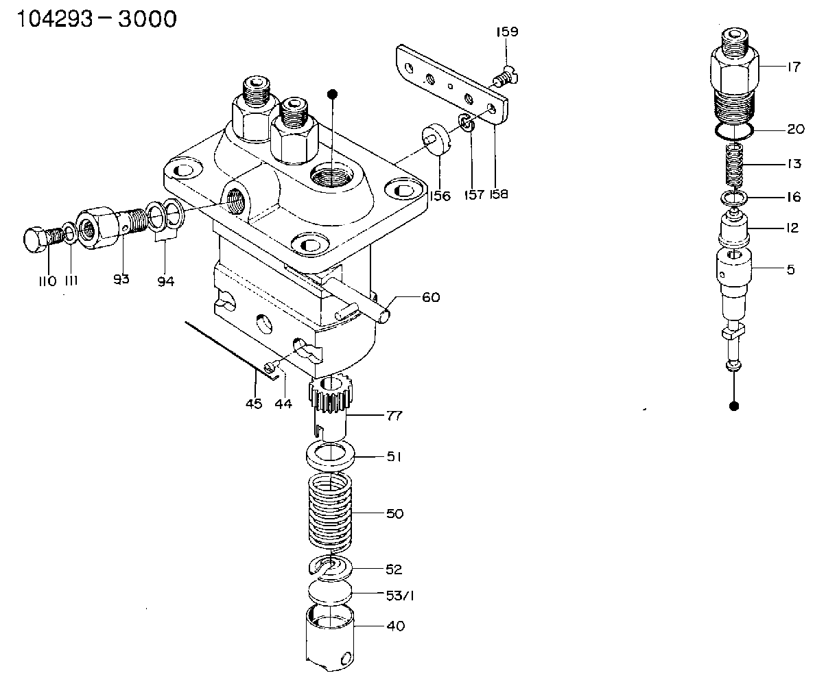
Start By:a. remove fuel transfer pump 1. Remove tachometer drive (3) from transfer pump cover (4).2. Remove bolts (1). Make a separation between cover (4) and pump body (2). 3. Remove lip-type seal (6) from the cover. Remove plug (5), seal, spring and plunger (bypass valve) from the cover. 4. Remove nut (10) from shaft (7). Remove gear (9) and key (11).5. Remove shaft (7) and gear (8) as a unit. Remove gear (8) from drive shaft (7) with a press.6. Remove idler gear (12). 7. Remove bushing (14), two lip-type seals and the bottom bearing from pump body (1).8. Remove check valve (13). Assemble Fuel Transfer Pump
1. Install bushing (4) in body (3) with Tooling (B). The bushing must not be extended above the (gear) surface of the body.2. Install the check valve in the body with Tooling (A).3. Install lip-type seal (5) with Tooling (C). Install the seal until it is 24.6 0.5 mm (97 .02) from the bottom surface of body (3) and with the lip toward bushing (4) as shown.4. Install lip-type seal (6) with Tooling (D). Install the seal until it is 14.2 0.5 mm (.56 .02 in) from the bottom surface of body (3) and with the lip away from seal (5) as shown.5. Install bearing (7) in body (3) with Tooling (E). The bearing must be even with the surface of the pump body. 6. Heat gear (8) to a maximum temperature of 316°C (600°F). Install gear (8) on shaft (11) until dimension (X) is 49.71 0.25 mm (1.957 0.10 in).7. Install the drive shaft and gear in body (3). Install key, gear (10) and nut (9). Tighten the nut to a torque of 28 7 N m (22 5 lb ft).8. Install idler gear (12) in body (3).9. Install lip-type seal (2) with Tooling (C). Install the seal until it is 3.8 0.5 mm (.15 .02 in) from the top surface of cover (1) with the lip toward the inside as shown. 10. Install plunger (14) (bypass valve), spring (15), seal plug (13) in pump cover (1). Tighten plug (13) to a torque of 28 4 N m (27 3 lb ft).11. Put 7M-7260 Liquid Gasket Material on the surface of cover (1). Install cover (1) on pump body.
Do not let the liquid gasket enter the pump.
The drive shaft must turn freely after the bolts that hold the transfer pump together are tightened.12. Install tachometer drive on transfer pump cover (1).End By:a. install fuel transfer pump
Have questions with 029998-0010?
Group cross 029998-0010 ZEXEL
Isuzu
029998-0010
9 442 610 161
8944281600
PLATE
Ishikawajima-H
029998-0010
9 442 610 161
131296530
PLATE
Fuji-Heavy
029998-0010
9 442 610 161
2286311008
PLATE
Ishikawajima-S
029998-0010
9 442 610 161
131296530
PLATE
Kubota
029998-0010
9 442 610 161
1538151491
PLATE
029998-0010
9 442 610 161
1526151491
PLATE
Toyo-Sha
029998-0010
9 442 610 161
81185014000
PLATE
029998-0010
9 442 610 161
81185014010
PLATE
Kubota
029998-0010
9 442 610 161
1538151491
PLATE