Information plain washer
BOSCH
9 421 610 554
9421610554
ZEXEL
154206-2400
1542062400
ISUZU
1157294440
1157294440
Rating:
Include in ###:
Number on scheme 161

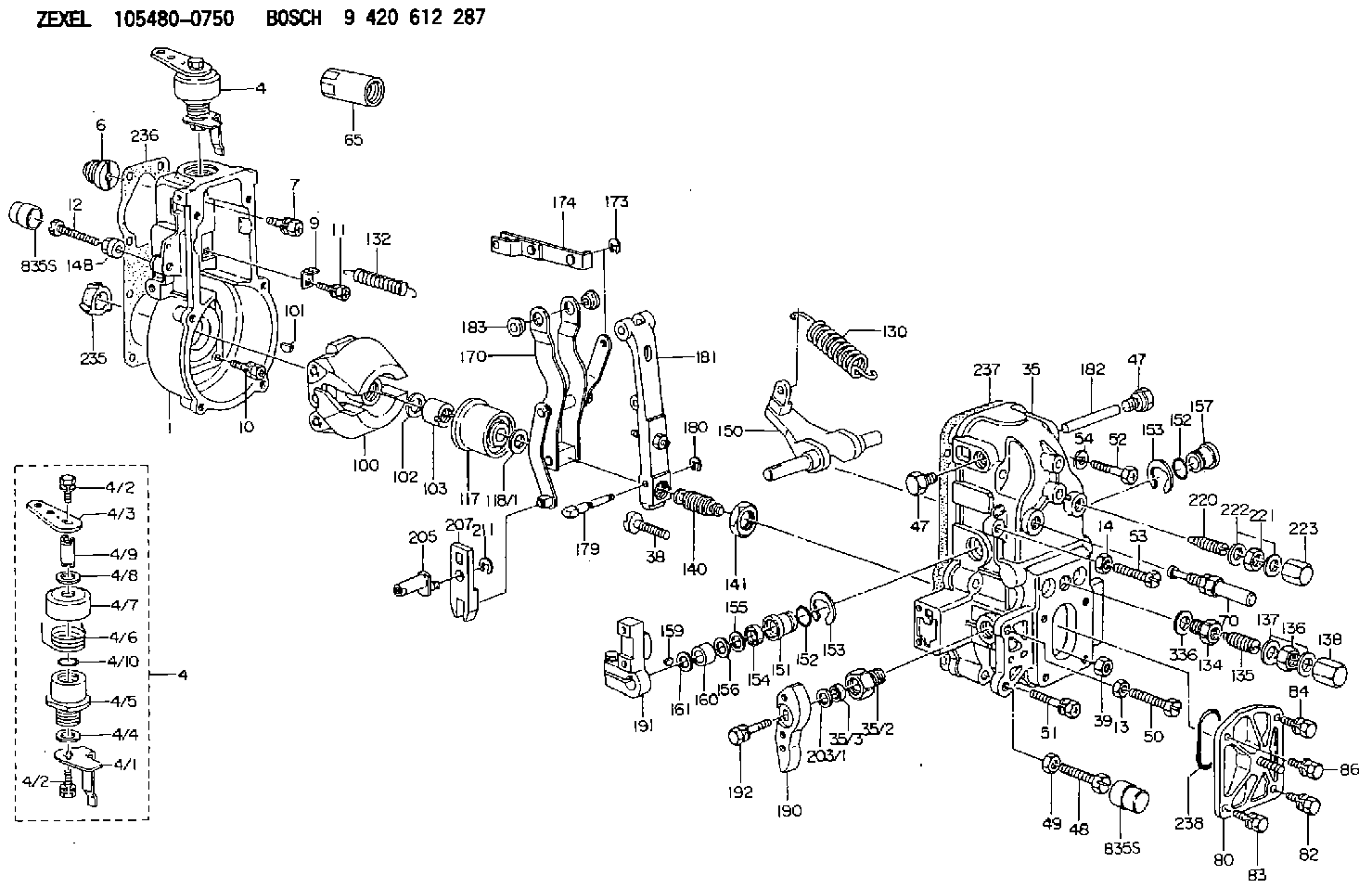
1054800750
as PLAIN WASHER
D20.5&12.2T1
1054870630
as PLAIN WASHER
1054870810
as PLAIN WASHER
D20.5&12.2T1
1054871100
as PLAIN WASHER
1054871160
as PLAIN WASHER
D20.5&12.2T1
1054871630
as PLAIN WASHER
1054871790
as PLAIN WASHER
D20.5&12.2T1
1054872450
as PLAIN WASHER
1054872490
as PLAIN WASHER
D20.5&12.2T1
1054872611
as PLAIN WASHER
1054872613
as PLAIN WASHER
D20.5&12.2T1
1054872800
as PLAIN WASHER
1054872840
as PLAIN WASHER
D20.5&12.2T1
Cross reference number
Zexel num
Bosch num
Firm num
Name
154206-2400
9 421 610 554
1157294440 ISUZU
PLAIN WASHER
C 14GJ WASHER GOV
C 14GJ WASHER GOV
154206-2400
9 421 610 554
228814070A HINO
PLAIN WASHER
C 14GJ WASHER GOV
C 14GJ WASHER GOV
154206-2400
9 421 610 554
ME704525 MITSUBISHI
PLAIN WASHER
C 14GJ WASHER GOV
C 14GJ WASHER GOV
154206-2400
9 421 610 554
1921599008 NISSAN-DIESEL
PLAIN WASHER
C 14GJ WASHER GOV
C 14GJ WASHER GOV
Information:
Introduction
The following procedures contain crucial information on correctly installing the new 162-2501 Hose As and the 258-8917 Protection Sleeve .Note: The 162-2501 Hose As replaces 107-7942 Tube As .Installation Procedure of the Hose Assembly
Illustration 1 g01230674
Remove old 162-2501 Hose As (1). Keep all of the manifold and pump fittings attached.Note: Step 2 is only for 3408E engines.
Remove the 7W-6492 Pipe Plug (2) from the aftercooler housing (3). Install the 8T-6762 Pipe Plug into the aftercooler housing.
Illustration 2 g01230678
Note: Always tighten the fittings with your hand before you use a wrench. Support the hose and the elbow while you tighten in order to avoid the following damage: twisting, kinking and side loading.
Loosen elbow (4) and jam nut (5) .
Hand tighten the nut on the hose (5) to the elbow (4) .
Install the other end of the hose (6) to the pump fitting. Tighten the nut to 125 15 N m (90 11 lb ft).
Hold the elbow (4) in position and torque the jam nut to 145 15 N m (105 11 lb ft).
Support the elbow (4). Tighten the nut (5) on the hose to 125 15 N m (90 11 lb ft).
Illustration 3 g01230687
Illustration 3 shows the routing of the 162-2501 Hose As (8). The hose is routed from the rail, around the rear of the fuel transfer pump (9), and into the 90 degree fitting (7) that is installed into the pump.
Illustration 4 g01230689
Some 3408 engines use an aftercooler that is mounted high. The mounting bracket (10) is located close to the 162-2501 Hose As (8). If there is not enough clearance to install the protective sleeve, the hose will need to be loosened and the hose will need to be repositioned. Refer to 5 for repositioning of the hose.
Illustration 5 g01230690
The hose must be realigned if any of the following conditions exist:
Not enough clearance against the fuel transfer pump
Not enough clearance against the support bracket
Loosen the end of the hose (12) .
Loosen the elbow and the jam nut (11). Note: Do not remove the hose.
Reposition the hose in order to acquire the desired clearance.
Hold the end of the hose (12). Tighten the jam nut (11) .Tighten the jam nut to the following torque. ... 143 15 N m (105 11 lb ft)Note: Locking pliers can be used on the crimped portion of the hose. Do not use the locking pliers on the braided portion of the hose. This will damage the hose which will cause a failure.
Tighten the end of the hose (12) .Tighten the end of the hose to the following torque. ... 125 15 N m (92 11 lb ft)Note: If adjustment of the hose is required, make sure that the hose is not bent. Also, ensure that the hose is not twisted. If these conditions exist the PTFE liner can be damaged.Installation of the Protective Sleeve Over the New Hose Assembly
Illustration 6 g01106118
Top viewInstallation of a protective sleeve for the hoses of the
Have questions with 154206-2400?
Group cross 154206-2400 ZEXEL
Isuzu
154206-2400
9 421 610 554
1157294440
PLAIN WASHER
Hino
154206-2400
9 421 610 554
228814070A
PLAIN WASHER
Mitsubishi
154206-2400
9 421 610 554
ME704525
PLAIN WASHER
Nissan-Diesel
154206-2400
9 421 610 554
1921599008
PLAIN WASHER