Information plain washer
BOSCH
9 421 617 074
9421617074
ZEXEL
154206-0200
1542060200
ISUZU
9813254880
9813254880
Rating:
Include in ###:
Number on scheme 239

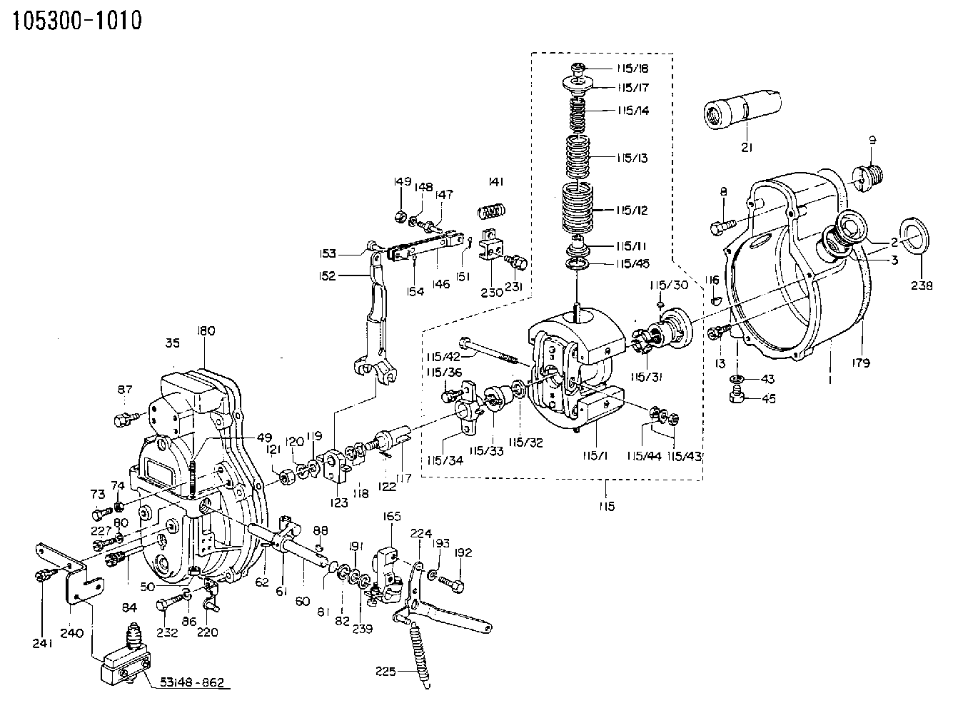
1053001010
as PLAIN WASHER
D19.5&11.2T1.0
1053060431
as PLAIN WASHER
1053060434
as PLAIN WASHER
D19.5&11.2T1.0
1053060621
as PLAIN WASHER
1053060624
as PLAIN WASHER
D19.5&11.2T1.0
1053060840
as PLAIN WASHER
1053060861
as PLAIN WASHER
D19.5&11.2T1.0
1054001500
as PLAIN WASHER
1054001520
as PLAIN WASHER
D19.5&11.2T1.0
Cross reference number
Zexel num
Bosch num
Firm num
Name
154206-0200
9 421 617 074
9813254880 ISUZU
PLAIN WASHER
C 14GJ WASHER GOV
C 14GJ WASHER GOV
154206-0200
9 421 617 074
6059130900 HINO
PLAIN WASHER
C 14GJ WASHER GOV
C 14GJ WASHER GOV
154206-0200
9 421 617 074
228813450A HINO
PLAIN WASHER
B C 14GJ WASHER GOV
B C 14GJ WASHER GOV
154206-0200
9 421 617 074
S228813450A HINO
PLAIN WASHER
B C 14GJ WASHER GOV
B C 14GJ WASHER GOV
154206-0200
9 421 617 074
ME704608 MITSUBISHI
PLAIN WASHER
C 14GJ WASHER GOV
C 14GJ WASHER GOV
154206-0200
9 421 617 074
1685490001 NISSAN-DIESEL
PLAIN WASHER
C 14GJ WASHER GOV
C 14GJ WASHER GOV
154206-0200
9 421 617 074
1312961510 ISHIKAWAJIMA-S
PLAIN WASHER
C 14GJ WASHER GOV
C 14GJ WASHER GOV
154206-0200
9 421 617 074
EZ40060XX167 M.BISHI-HI.-NAG
PLAIN WASHER
C 14GJ WASHER GOV
C 14GJ WASHER GOV
154206-0200
9 421 617 074
9421617074 BOSCH
PLAIN WASHER
C 14GJ WASHER GOV
C 14GJ WASHER GOV
Information:
Safety Section
Care must be taken to ensure that fluids are contained during performance of inspection, maintenance, testing, adjusting, and repair of the product. Be prepared to collect the fluid with suitable containers before opening any compartment or disassembling any component containing fluids.Refer to Special Publication, NENG2500, "Dealer Service Tool Catalog" for tools and supplies suitable to collect and contain fluids on Cat® products.Dispose of all fluids according to local regulations and mandates.
Illustration 1 g00104545Prevent the machine from movement. Park the machine on a level surface.Attach a "Do Not Operate" warning tag or a similar warning tag to the start switch or to the controls before you service the equipment. These warning tags (Special Instruction, SEHS7332) are available from your Caterpillar dealer.Required Parts
Table 1 contains the parts needed to complete the installation of the new DEF filter.Note: Only one DEF filter group is required per engine. Use Table 2 to determine which filter is the appropriate filter for each DEF header. Illustration 2 shows the location of the DEF header part number.
Table 1
Part Number Part Description Qty
378-3187 Diesel Exhaust Fluid Filter Gp 1
423-3251 Connector 1
391-5262 Gasket 1
425-0385 Filter As 1
452-6055 Filter Base As 1
453-1604(1) Diesel Exhaust Fluid Filter Gp 1
453-1605(1) Diesel Exhaust Fluid Filter Gp 1
453-1606(1) Diesel Exhaust Fluid Filter Gp 1
(1) Use Table 2 to choose the correct part that corresponds to the DEF header
Illustration 2 g03745839
(1) Location of DEF heater part number
Table 2
DEF Heater Part Number Required DEF Filter
434-3241 453-1604
434-3242 453-1605
434-3243 453-1606 Installation Procedure
Ensure that the area around the DEF heater is clean and free from debris.
Remove manifold DEF heater from DEF tank. Refer to Disassembly and Assembly, Manifold (DEF Heater) - Remove and Install for the correct procedure.
Illustration 3 g06013988
Typical example
Position filter base assembly (3) to DEF heater (2). Install screws (1) to filter base assembly (3). Tighten the self-tapping screws (1) securely.Note: Each half of the adapter has two small locking tabs that secure to the bottom side of the DEF heater.
Remove existing filter from the pickup pipe on manifold DEF heater. Refer to Disassembly and Assembly, Manifold (DEF Heater) - Remove and Install for the correct procedure.
Install a new filter to the pickup pipe on manifold DEF heater. Refer to Disassembly and Assembly, Manifold (DEF Heater) - Remove and Install for the correct procedure.
Illustration 4 g06013992
Typical example
Position the correct DEF filter (5) to the filter base assembly (3). Install band clamp (4). Tighten the band clamp to a torque
Have questions with 154206-0200?
Group cross 154206-0200 ZEXEL
Isuzu
154206-0200
9 421 617 074
9813254880
PLAIN WASHER
Hino
154206-0200
9 421 617 074
6059130900
PLAIN WASHER
154206-0200
9 421 617 074
228813450A
PLAIN WASHER
154206-0200
9 421 617 074
S228813450A
PLAIN WASHER
Mitsubishi
154206-0200
9 421 617 074
ME704608
PLAIN WASHER
Nissan-Diesel
154206-0200
9 421 617 074
1685490001
PLAIN WASHER
Ishikawajima-S
154206-0200
9 421 617 074
1312961510
PLAIN WASHER
M.Bishi-Hi.-Nag
154206-0200
9 421 617 074
EZ40060XX167
PLAIN WASHER
Bosch
154206-0200
9 421 617 074
9421617074
PLAIN WASHER