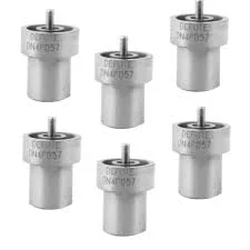
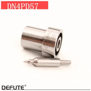
Information pintle nozzle
BOSCH
9 432 610 284
9432610284
ZEXEL
105007-1260
1050071260

Rating:
Compare Prices: .
As an associate, we earn commssions on qualifying purchases through the links below

093400-5571/093400-5640/105007-1260 Diesel Fuel Injector Parts Nozzle DN4PD57 for T0Y0TA Motor2L
Generic Is customized: yes || Material type: Steel products || Item length: 3 || Origin: Mainland China || Oem no.: DN4PD57
Generic Is customized: yes || Material type: Steel products || Item length: 3 || Origin: Mainland China || Oem no.: DN4PD57

12PCS DN0PDN128 DN10PDN135 DN0PD619 DN4PD3 Diesel Fuel Injector DN PD PDN - (Color: DN4PD57)
Generic Color: DN4PD57
Generic Color: DN4PD57
You can express buy:
USD 20.16
19-06-2025
19-06-2025
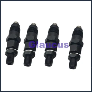
Original 4pcs New Fuel Injector Sprayer Nozzle 2l 3l Dn4pd57 093400-5571 1050071260 2362059045 For Hiace Hilux High Quality
USD 81
13-05-2025
13-05-2025
2L engine fuel injector Injection Nozzle for VW Volkswagen TARO 2446 2.4 D 1989-1997 093400-5571 105007-1260
USD 18
13-05-2025
13-05-2025
Free Shipping 4Pieces/Lot DN4PD57 Injector nozzle 093400-5571 ND-DN4PD57 105007-1260
Images:
USD 25.35

[29-May-2025]
USD 10.46

[16-May-2025]
USD 3.5

[28-Apr-2025]
USD 40

[11-Nov-2022]
Cross reference number
Zexel num
Bosch num
Firm num
Name
Information:
3. Disconnect all fuel injection lines (2) from the pump housing. Put caps and plugs in all lines or openings.4. Disconnect sensing line (1) from fuel ratio control.5. Disconnect fuel supply line (3) from fuel injection pump housing.6. Remove the two bolts (5) that hold bracket to the cylinder block.7. Remove the bolts (4) that hold injection pump housing to accessory drive housing. Remove the fuel injection pump housing and governor. Weight of pump housing and governor is 70 lb. (32 kg).Install Fuel Injection Pump Housing And Governor
1. Remove plugs and caps from lines and openings. Put the fuel injection pump housing and governor in position on engine, and install the bolts in accessory drive housing (1).2. Install the two bolts in bracket (2).3. Connect the fuel injection lines to the pump housing. Tighten the nuts to 30 5 lb.ft. (4.1 0.7 mkg).4. Connect fuel supply line to pump housing.5. Connect the sensing line to fuel ratio control.6. Connect control linkage for the governor.7. Check the camshaft timing for the fuel injection pumps. See FUEL INJECTION PUMP CAMSHAFT TIMING in TESTING AND ADJUSTING.Separation Of Governor From Fuel Injection Pump Housing
start by: a) remove fuel injection pump housing and governorb) remove fuel ratio controlc) remove fuel shutoff solenoid1. Remove the idle screw cover, plate, and housing. 2. Remove the screw (2) from rack stop collar.3. Remove rack stop collar (3), spring, and collar.4. Remove the bolts (1) that hold the governor to the fuel injection pump housing. Remove the governor housing.5. Remove the spring and seat assembly from the governor housing. 6. Remove the washer-type spring (5).7. Remove the three bolts (4) and lock.8. Remove the cylinder and weight assembly (6).Connection Of Governor To Fuel Injection Pump Housing
1. Put the cylinder and weight assembly (2) in position on the injection pump housing so the opening in piston (1) is engaged with groove in rack (3). Install the lock and three bolts. 2. Install the washer-type spring (4) so inside diameter of spring will be against the guide in governor housing (5).3. Install the spring and seat assembly in the governor housing. Put the governor housing (5) in position on pump housing, and install the bolts.4. Put the spring, collar, and rack stop collar in position, and install the screw in rack stop collar. Install idle screw housing.end by: a) install fuel shutoff solenoidb) install fuel injection pump housing and governorc) make adjustments to rack and governor as given in TESTING AND ADJUSTINGd) install fuel ratio control