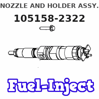
Information nozzle and holder assy.
BOSCH
9 430 613 713
9430613713
ZEXEL
105158-2322
1051582322
ISUZU
8970796530
8970796530
Rating:
Compare Prices: .
As an associate, we earn commssions on qualifying purchases through the links below

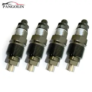
4pcs 9430613713 8971406240 8970796530 8-97140624-0
EDWREGIG
EDWREGIG

Set Of 4 Fuel Injector 9430613713 8971406240 8970796530 Compatible For Isuzu Engine 4JG1 4JG2 105007-1240
TQUBEUMI Precise fuel injection with excellent fuel atomization effect, which improves the efficiency of the fuel injection work. || It is easy to install, saving maintenance time and costs. With a long service life, it reduces the replacement frequency. || The fuel injection pressure is stable, ensuring the smooth operation of the engine and enhancing the fuel economy of the engine. || Thanks to the advanced manufacturing process, the product quality is stable. It also has good cold start performance, making it fearless of severe cold weather. || Set Of 4 Fuel Injector 9430613713 8971406240 8970796530 Compatible For Isuzu Engine 4JG1 4JG2 105007-1240
TQUBEUMI Precise fuel injection with excellent fuel atomization effect, which improves the efficiency of the fuel injection work. || It is easy to install, saving maintenance time and costs. With a long service life, it reduces the replacement frequency. || The fuel injection pressure is stable, ensuring the smooth operation of the engine and enhancing the fuel economy of the engine. || Thanks to the advanced manufacturing process, the product quality is stable. It also has good cold start performance, making it fearless of severe cold weather. || Set Of 4 Fuel Injector 9430613713 8971406240 8970796530 Compatible For Isuzu Engine 4JG1 4JG2 105007-1240

4PCS Fuel Injector Compatible with Isuzu Engine 4JG1 4JG2 FHD20Z5 9430613713 8971406240 8970796530 8-97140624-0
HNUSLIPZ Easy installation: The design of the nozzle assembly considers the convenience of installation, and the user can easily complete the installation || Strong stability: the automobile injector can maintain stable work for a long time under harsh conditions, and is not prone to failure, extending the service life || Fast response: The fuel injector can quickly respond to the instructions of the engine control unit, and complete the fuel injection in a very short time to ensure the stable operation of the engine || Efficient atomizing fuel: Automotive fuel injection devices use special design and spray technology to make fuel and air fully mixed, allowing the vehicle to accelerate more smoothly and reduce fuel consumption || 4PCS Fuel Injector Compatible With Isuzu Engine 4JG1 4JG2 FHD20Z5 9430613713 8971406240 8970796530 8-97140624-0
HNUSLIPZ Easy installation: The design of the nozzle assembly considers the convenience of installation, and the user can easily complete the installation || Strong stability: the automobile injector can maintain stable work for a long time under harsh conditions, and is not prone to failure, extending the service life || Fast response: The fuel injector can quickly respond to the instructions of the engine control unit, and complete the fuel injection in a very short time to ensure the stable operation of the engine || Efficient atomizing fuel: Automotive fuel injection devices use special design and spray technology to make fuel and air fully mixed, allowing the vehicle to accelerate more smoothly and reduce fuel consumption || 4PCS Fuel Injector Compatible With Isuzu Engine 4JG1 4JG2 FHD20Z5 9430613713 8971406240 8970796530 8-97140624-0
You can express buy:
USD 86.67
10-05-2025
10-05-2025
4pcs Fuel Injector 9430613713 8971406240 8970796530 8-97140624-0 For Isuzu Engine 4JG1 4JG2, for TCM Forklift FHD20Z5 FHD30Z5
USD 24.46
28-04-2025
28-04-2025
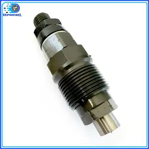
1pc Original Fuel Injector 8971406240 8970796530 8-97140624-0 9430613713 For Isuzu 4JG1 4JG2 Car Accessories
Images:
USD 24.46

[28-Apr-2025]
Include in #1:
101402-7200
as NOZZLE AND HOLDER ASSY
Include in #2:
104746-1300
as NOZZLE AND HOLDER ASSY
Cross reference number
Zexel num
Bosch num
Firm num
Name
105158-2322
8970796530 ISUZU
NOZZLE AND HOLDER ASSY.
4JG2 K 53KP NOZZLE & HOLDER ASSY N&NH KDA-P N&NH
4JG2 K 53KP NOZZLE & HOLDER ASSY N&NH KDA-P N&NH
Information:
Test Procedure
System Operation
The SLC 5/04 diagnostic indicators are located on the front of the following components: Power Supply, CPU and I/O Modules.The diagnostic indicators help trace the source of the fault. Faults can be found in the following components: Input devices, Output devices, Wiring and The controller.The thermocouple module has five LED indicators. Four of the LED indicators are "Channel Status" indicators. The "Channel Status" indicators are numbered according to the channel. One of the LED indicators is a "Module Status" indicator. You can recover from the "Channel Status" errors.Diagnostics are displayed on the "Module Status" LED indicator. Operating errors are displayed on the "Module Status" LED indicator. Problems may be detected during powerup or problems may be detected during operation. When an error occurs the module will not communicate with the processor. The channel is disabled and the data is cleared.
Illustration 1 g00563580
Diagram of the LED indicators
Illustration 2 g00563584
Diagram of the thermocouple module
Illustration 3 g00563586
Schematic of the thermocouple moduleFunctional Test
The "Module Status" LED is on. The module is operating normally. Stop.
The "Channel Status" LED is on. The module is operating normally. Stop.
The "Module Status" LED is off. The module is in a fault condition. Proceed to 6.
The "Channel Status" LED is off. The channel is not enabled. This is normal if the sensor is not wired.
The "Channel Status" LED is blinking. The module is in a fault condition. Proceed to 10.
Check the electrical connectors and check the wiring.
Bodily contact with electrical potential can cause bodily injury or death.To avoid the possibility of injury or death, ensure that the main power supply has been disconnected before performing any maintenance or removing any modules.
Disconnect the power supply.
Check the electrical connectors and check the wiring for damage or bad connections.
Verify that all modules are properly seated.
Verify the status of the LED on the SLC 5/04.The results of the preceding procedure are in the following list:
All of the components are fully installed. All of the components are free of corrosion. All of the components are free of damage. All of the modules are properly seated. Proceed to 7.
The components are not fully installed. The components are not free of corrosion. The components are damaged. All of the modules are not properly seated. Repair the component. Verify that the repair resolves the problem. STOP.
Check the LED indicator on the module.
Connect the power supply.
Cycle the power to the module.The results of the preceding procedure are in the following list:
No errors are displayed on the LED indicators. Stop.
Errors are displayed on the LED indicators. Proceed to 8.
Check the module for a fault.
Bodily contact with electrical potential can cause bodily injury or death.To avoid the possibility of injury or death, ensure that the main power supply has been disconnected before performing any maintenance or removing any modules.
To avoid potential damage to the processor, handle all modules by the ends of the carrier or edges of the plastic housing. Skin oil or dirt can corrode metallic surfaces, inhibiting electrical contact.
Disconnect the power supply.
Remove the module from the chassis.Reference: Maintenance