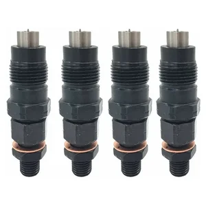
Information nozzle and holder assy.
BOSCH
9 430 612 750
9430612750
ZEXEL
105148-1560
1051481560
MITSUBISHI
MD338904
md338904

Rating:
Compare Prices: .
As an associate, we earn commssions on qualifying purchases through the links below

4pcs MD338904 Fuel Injectors Nozzle Compatible For Mitsubishi L200 K7-T K6-T 2.5D K64T 4D56 8V 2477cc 1996-2007 105148-1560
ZKKPJTCI High dynamic flow range, anti-clogging, anti-pollution ability, and long service life to ensure the reliability and durability of the fuel injector. || Made of high-pressure resistant and high-quality materials to ensure good sealing effect under high-pressure and high-temperature environment. || Precise manufacturing technology is adopted to ensure that the fuel can be evenly and accurately injected into the combustion chamber of the engine. || It is helpful to realize the accurate fuel supply of the engine, improve the fuel economy and emission performance, and meet the needs of different fuels. || 4pcs MD338904 Fuel Injectors Nozzle Compatible For Mitsubishi L200 K7-T K6-T 2.5D K64T 4D56 8V 2477cc 1996-2007 105148-1560
ZKKPJTCI High dynamic flow range, anti-clogging, anti-pollution ability, and long service life to ensure the reliability and durability of the fuel injector. || Made of high-pressure resistant and high-quality materials to ensure good sealing effect under high-pressure and high-temperature environment. || Precise manufacturing technology is adopted to ensure that the fuel can be evenly and accurately injected into the combustion chamber of the engine. || It is helpful to realize the accurate fuel supply of the engine, improve the fuel economy and emission performance, and meet the needs of different fuels. || 4pcs MD338904 Fuel Injectors Nozzle Compatible For Mitsubishi L200 K7-T K6-T 2.5D K64T 4D56 8V 2477cc 1996-2007 105148-1560

You can express buy:
USD 44.53
29-06-2025
29-06-2025
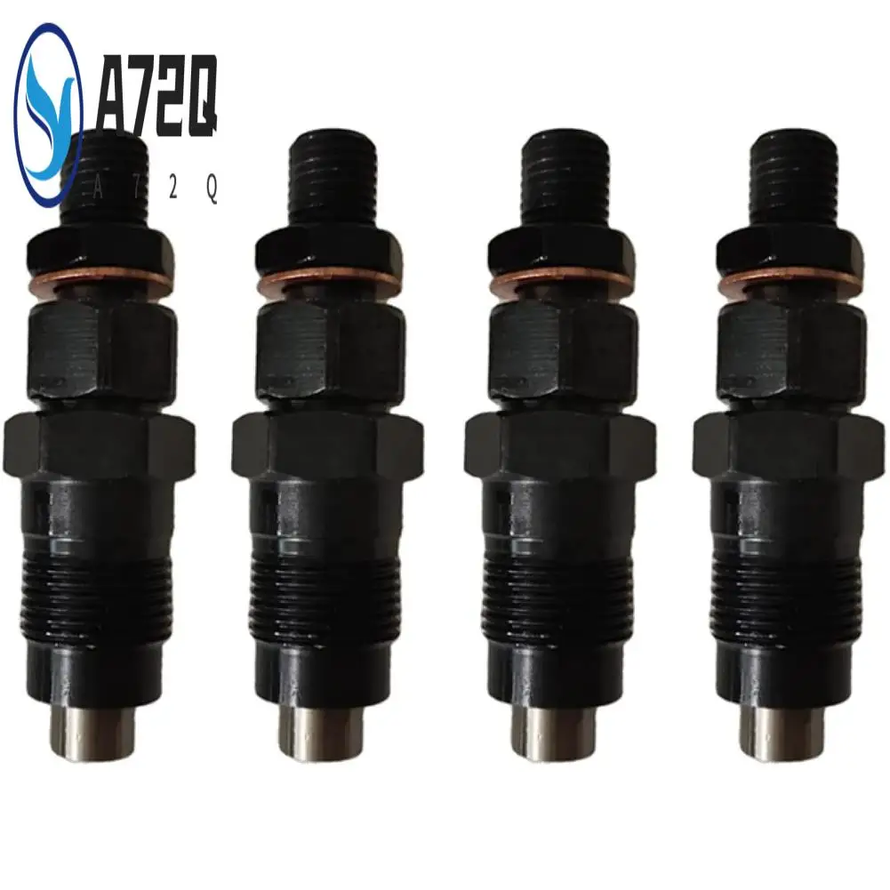
4Pcs Fuel Injector Nozzle for Mitsubishi L200 K7-T K6-T 2.5D K64T 4D56 8V 2477Cc 1996-2007 MD338904 105148-1560
USD 62.79
19-06-2025
19-06-2025
A72Q-4Pcs Fuel Injector Nozzle For Mitsubishi L200 K7-T K6-T 2.5D K64T 4D56 8V 2477Cc 1996-2007 MD338904 105148-1560
Images:
USD 62.79

[19-Jun-2025]
USD 85.49

[14-Jun-2025]
USD 59.74

[14-Jun-2025]
Include in #2:
104745-8590
as NOZZLE AND HOLDER ASSY
Cross reference number
Zexel num
Bosch num
Firm num
Name
105148-1560
MD338904 MITSUBISHI
NOZZLE AND HOLDER ASSY.
4D56 K 53KJ NOZZLE & HOLDER ASSY N&NH KCA-P N&NH
4D56 K 53KJ NOZZLE & HOLDER ASSY N&NH KCA-P N&NH
Information:
3. Turn the engine to the top center (TC) compression stroke for the No. 1 piston.4. Remove bolts (1), cover assembly (2) and the gasket from the front housing. 5. Remove two bolts (3). Carefully remove thrust plate (4) and the camshaft assembly from the engine.6. Remove drive gear (5) from the camshaft with a press. Remove the woodruff key from the camshaft. The following steps are for the installation of the camshaft.7. Install the woodruff key in the camshaft. Heat drive gear (5) to a maximum temperature of 316°C (600°F). Do not use a torch to heat the drive gear. Install the drive gear on the camshaft, and allow it to cool.
Camshaft timing is very important. When the camshaft assembly is installed, be sure the No. 1 piston is at top center (TC) of the compression stroke. The timing marks on the camshaft drive gear, the idler gear and the crankshaft idler gear must be in alignment as shown in Illustration C21075P5. For more information regarding timing of the engine, see the topic "Front Gear Group" in the 3114 & 3116 Diesel Truck Engine Specifications module, Form No. SENR6436.
8. Apply clean engine oil on the lobes and journals of the camshaft. Carefully install the camshaft assembly in the cylinder block.9. Put thrust plate (4) in position, and install bolts (3) that hold it.10. Be sure the mating surfaces of the front housing and cover assembly (2) are thoroughly clean. Apply 8C8422 Sealant to the cover assembly sealing surface. Spread the sealant uniformly and around each bolt hole. The cover assembly must be installed on the front housing within ten minutes of sealant application.11. Put the gasket and cover assembly (2) in position on the front housing. Install bolts (1) that hold the cover assembly to the front housing.12. Install the vibration damper and the crankshaft pulley. See the topic "Remove & Install Vibration Damper, Crankshaft Pulley & Crankshaft Front Seal" in this module.13. Install the governor and fuel transfer pump. See the topic "Remove & Install Governor & Fuel Transfer Pump" in this module.End By:a. Install lifter assemblies