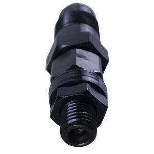
Information nozzle and holder assy.
BOSCH
9 430 610 135
9430610135
ZEXEL
105148-1221
1051481221
NISSAN-DIESEL
1660063G01
1660063g01

Rating:
Compare Prices: .
As an associate, we earn commssions on qualifying purchases through the links below

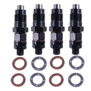
DoraKvi 4-Pieces 16600-63G01 1660063G01 Fuel Injector Compatible with Navara QD32 D22 3.2L Engine
DoraKvi 🌟 Part Name :Fuel Injector || 🌟 Part Number : 16600-63G01 1660063G01 || 🌟 Application : Compatible with Navara QD32 D22 3.2L Engine || ✅ Accurate ✅- In Order To Avoid Unnecessary Return. Please follow the old part number and machine model to find the right product, if you are not sure, please contact us, we are more than happy to provide services. || 💠 Reliable performance 💠-DoraKvi- our products have been carefully designed and tested, with high reliability and stability, can maintain good working condition for a long time.
DoraKvi 🌟 Part Name :Fuel Injector || 🌟 Part Number : 16600-63G01 1660063G01 || 🌟 Application : Compatible with Navara QD32 D22 3.2L Engine || ✅ Accurate ✅- In Order To Avoid Unnecessary Return. Please follow the old part number and machine model to find the right product, if you are not sure, please contact us, we are more than happy to provide services. || 💠 Reliable performance 💠-DoraKvi- our products have been carefully designed and tested, with high reliability and stability, can maintain good working condition for a long time.


105148-1221 Fuel Injection Nozzle 8Pcs
DFGUFG [Product compatibility]: The OE number of this product is 105148-1221 || [Enhanced Fuel Efficiency & Power Output: Precision-engineered fuel injectors optimize spray patterns for improved combustion efficiency, directly boosting mileage while maintaining stable engine performance across all RPM ranges || [Easy to install and affordable]: Each fuel injector meets factory standard specifications, is simple and convenient to install, has higher combustion efficiency, and can effectively reduce fuel consumption || [High-quality materials for better performance]: The injectors are made of high-quality materials and advanced manufacturing processes to ensure durability and service life, allowing your engine to run smoothly for a long time || [Guaranteed Engine Performance]: This product is one of the key components of electronic fuel injection engines, helping to improve engine performance
DFGUFG [Product compatibility]: The OE number of this product is 105148-1221 || [Enhanced Fuel Efficiency & Power Output: Precision-engineered fuel injectors optimize spray patterns for improved combustion efficiency, directly boosting mileage while maintaining stable engine performance across all RPM ranges || [Easy to install and affordable]: Each fuel injector meets factory standard specifications, is simple and convenient to install, has higher combustion efficiency, and can effectively reduce fuel consumption || [High-quality materials for better performance]: The injectors are made of high-quality materials and advanced manufacturing processes to ensure durability and service life, allowing your engine to run smoothly for a long time || [Guaranteed Engine Performance]: This product is one of the key components of electronic fuel injection engines, helping to improve engine performance
You can express buy:
USD 42.61
19-05-2025
19-05-2025
The 16600-63G01 diesel fuel injector is suitable for the Nissan NAVARA QD32 D22 TD42TI 3.2L.
USD 42.61
19-05-2025
19-05-2025
The 16600-63G01 diesel fuel injector is suitable for the Nissan NAVARA QD32 D22 TD42TI 3.2L.
Include in #1:
101443-9042
as NOZZLE AND HOLDER ASSY
Include in #2:
104701-2001
as NOZZLE AND HOLDER ASSY
Cross reference number
Zexel num
Bosch num
Firm num
Name
105148-1221
1660063G01 NISSAN-DIESEL
NOZZLE AND HOLDER ASSY.
TD27T K 53KJ NOZZLE & HOLDER ASSY N&NH KCA-P N&NH
TD27T K 53KJ NOZZLE & HOLDER ASSY N&NH KCA-P N&NH
Information:
2. Turn the crankshaft until two pistons are at bottom center.3. Remove nuts (1) and the bearing caps. Push the rods and pistons up until the rings are out of the cylinder liners. 4. Remove pistons (2) and connecting rods from the cylinder liners.5. Do Steps 1 through 4 for the remainder of the pistons and connecting rods.Install Pistons And Connecting Rod Assemblies
1. Put clean engine oil on piston rings, connecting rod bearings and cylinder liners. 2. Use tool (A), and install piston (2) and the connecting rod in the cylinder liner. Be sure the number on the tab groove side of the connecting rod is on the opposite side from the camshaft.3. Install the bearing cap on the connecting rod with the number on the side of the bearing cap on the same side and same number as on the connecting rod.4. Put 2P2506 Thread Lubricant on the threads of the bolts. Install the nuts, and tighten them to a torque of 80 8 N m (60 6 lb.ft.). Put a mark on the nuts and cap, and tighten the nuts an extra 120°.5. Do Steps 1 through 4 for the remainder of the pistons and connecting rods.End By:a. install oil pumpb. install cylinder head assembly.Disassemble & Assemble Pistons And Connecting Rod Assemblies
Start By:a. remove pistons and connecting rod assemblies 1. Remove bearings (3) from the connecting rod and connecting rod cap.2. Remove retainer ring (1) and tool (A).3. Remove pin (2) and connecting rod (4) from the piston. 4. Remove piston rings (5) from the piston with tool (B). Clean the piston ring grooves on the pistons with an acceptable ring groove cleaning tool. See, Use Of Piston Pin Bearing Removal And Installation Tools, Special Instructions, Form No. SMHS7295.5. Heat connecting rod (4) in an oven to a temperature of 177° to 260°C (350° to 500°F). Never use a direct flame to heat a connecting rod. 6. Put connecting rod (4) in position on the base plate of tooling (C). Put a new rod pin bearing (6) on the adapter part of tooling (C). The old bearing is pushed out by tooling (C) as the new bearing is installed.7. Use tooling (C) to push the new bearing into the connecting rod until the push adapter of tooling (C) makes full contact with the connecting rod surface.8. Use a pin boring machine to make the rod pin bearing the correct size. The bore in the new rod pin bearing must be 50.830 0.008 mm (2.0012 .0003 in.).9. Check the clearance between the ends of the piston rings. See the topic, Pistons and Rings in the Specifications manual.10. Install the oil ring spring in the oil ring groove of the piston. The oil ring is to be installed over the spring with the oil ring end gap 180° from the oil ring spring joint.11. Install the oil ring on the piston with tool (B).12. Install the second (intermediate) piston ring with the side that