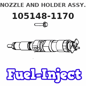
Information nozzle and holder assy.
BOSCH
9 430 610 172
9430610172
ZEXEL
105148-1170
1051481170
ISHIKAWAJIMA-S
131406360
131406360
Rating:
Compare Prices: .
As an associate, we earn commssions on qualifying purchases through the links below

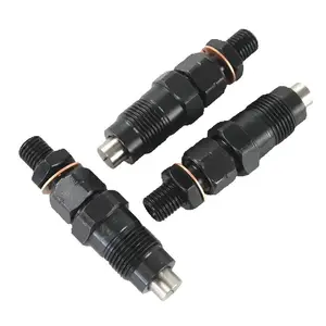
1pc DN4PDN117 131406360 131406440
BOUZQRBQT
BOUZQRBQT

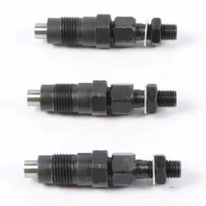
Tenlioshun 105148-1170 1051481170 Fuel Injector 4PCS Fits For Perkins 104-22 403C-15 403D-15 403D-15T 403C-17 403D-17 404C-22 404D-22 404C-22T 404D-22T Engine
Tenlioshun Part Name:Fuel Injector 105148-1170 1051481170 || Part Number:105148-1170 1051481170 9430613923 || APPlication: Compatible with Perkins 104-22 403C-15 403D-15 403D-15T 403C-17 403D-17 404C-22 404D-22 404C-22T 404D-22T Engine for New Holland TC30 TC45 TC55 L140 L150 L160 L213 L565 for Case SR160 || Please leave us physical address (home or office address) but not PO box address || Please double check the part number of your item matching information is for reference onlyIf you are unsure of the item please contact us before buying to avoid unnecessary return thanks!
Tenlioshun Part Name:Fuel Injector 105148-1170 1051481170 || Part Number:105148-1170 1051481170 9430613923 || APPlication: Compatible with Perkins 104-22 403C-15 403D-15 403D-15T 403C-17 403D-17 404C-22 404D-22 404C-22T 404D-22T Engine for New Holland TC30 TC45 TC55 L140 L150 L160 L213 L565 for Case SR160 || Please leave us physical address (home or office address) but not PO box address || Please double check the part number of your item matching information is for reference onlyIf you are unsure of the item please contact us before buying to avoid unnecessary return thanks!

You can express buy:
USD 47.43
29-06-2025
29-06-2025
3pcs 131406360 SBA131406360 Fuel Injector For New Holland Ford Tractor 1320 1520 New Car Accessories
USD 43.31
14-06-2025
14-06-2025
3x Fuel Injectors 131406360 SBA131406360 SBA131406490 for New Holland Ford Tractor 1320 1530 1620 w/ Shibaura N844 T854 Engine
USD 35.48
14-06-2025
14-06-2025
For Ford Tractors 131406360 131406440 Injector Nozzle 105007-1170 DN4PDN117
Images:
USD 35.55

[14-Jun-2025]
USD 358.47

[14-Jun-2025]
USD 214.02

[14-Jun-2025]
USD 51.92

[27-May-2025]
Include in #2:
104134-3000
as NOZZLE AND HOLDER ASSY
Cross reference number
Zexel num
Bosch num
Firm num
Name
105148-1170
131406360 ISHIKAWAJIMA-S
NOZZLE AND HOLDER ASSY.
N843 K 53KJ NOZZLE & HOLDER ASSY N&NH KCA-P N&NH
N843 K 53KJ NOZZLE & HOLDER ASSY N&NH KCA-P N&NH
Information:
Start By:a. remove valve covers 1. Remove bolts (1) that hold the valve cover bases to the cylinder head assembly. Remove valve cover bases (2). 2. Use tool (A) to loosen fuel injection line (3) from fuel injection nozzle (4). 3. Use tool (B) to loosen the nut at the fuel injection line adapter end. Remove inner fuel injection lines (3). Install caps and plugs on all fuel injection line openings to keep dirt out of the fuel system. 4. Remove bolts (5) that hold the rocker shaft assemblies to the cylinder head assembly.5. Remove rocker shaft assemblies (6). 6. Put identification marks on the push rods as to their location in the engine. Remove push rods (7). 7. Put identification marks on the bridges as to their location in the engine. Remove bridges (8) from the dowels on the cylinder head assembly.Install Rocker Shaft Assemblies And Push Rods
1. Put clean engine oil on the bridges and dowels. Install the original bridges in their respective locations. New bridges can be mixed.2. Install bridges (8) on the bridge dowels. While firmly pressing 0.5 to 4.5 kg (1 to 10 lb.) straight down on the top contact surface of the bridge, turn the adjusting screw clockwise until contact is made with the valve stem. Turn the screw an additional 20° to 30° (1/3 to 1/2 of 1 hex on nut). This will straighten the dowel in the guide and compensate for the slack in the threads. Hold the adjusting screw in this position, and tighten the locknut to a torque of 30 4 N m (22 3 lb.ft.). Install original push rods in their respective locations in the engine. New push rods can be mixed.3. Install push rods (7). 4. Put rocker shaft assemblies (6) in position on the cylinder head assembly.5. Put clean engine oil on the threads of bolts (5) that hold the shaft assemblies in place. Tighten the bolts first to a torque of 270 25 N m (200 18 lb.ft.). Start with the bolt in the center of the rocker shaft assembly. Tighten the bolts again to a torque of 450 20 N m (330 15 lb.ft.). Tighten the bolts again by hand to a torque of 450 20 N m (330 15 lb.ft.).
Do not cause damage to the O-ring seals on the inner fuel lines.
6. Install inner fuel injection lines (3). Tighten the fuel injection line adapter nuts (9) to a torque of 40 7 N m (30 5 lb.ft.) with tool (B).7. Tighten fuel injection line nut (10) to a torque of 40 7 N m (30 5 lb.ft.) with tool (A).8. Make adjustments to the valves until the intake valve clearance is 0.38 mm (.015 in.) and the exhaust valve clearance is 0.76 mm (.030 in.). See Valve Clearance Setting in Testing And Adjusting. Tighten the locknut to a torque of 30 4 N m (22 3 lb.ft.) and