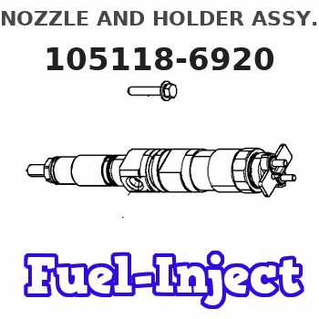
Information nozzle and holder assy.
BOSCH
9 430 613 530
9430613530
ZEXEL
105118-6920
1051186920
MITSUBISHI
ME440837
me440837
Rating:
Compare Prices: .
As an associate, we earn commssions on qualifying purchases through the links below

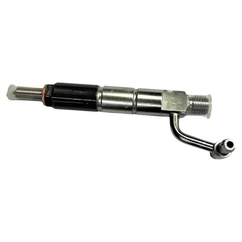
Diesel Fuel Injector ME440837 For Mitsubishi 6D34 Engine New Aftermarket Parts
GENERIC Package included:Original Diesel Fuel Injector*1 || Feature: Stable characteristics, high reliability. || We offer free repair or return or exchange service in the warranty. || Tips: Please check the old part number or the model of the applicable machine before purchasing! || Warm reminder: If you have any questions, please feel to contact us. We will reply within 24 hours and help solve the problem.
GENERIC Package included:Original Diesel Fuel Injector*1 || Feature: Stable characteristics, high reliability. || We offer free repair or return or exchange service in the warranty. || Tips: Please check the old part number or the model of the applicable machine before purchasing! || Warm reminder: If you have any questions, please feel to contact us. We will reply within 24 hours and help solve the problem.

6D34 Injector ME440837 for Excavator SK200-6 SK230-6 SK200-6E SK230-6E
Generic
Generic

105118-6920 Fuel Injection Nozzle 8Pcs
DFGUFG [Product compatibility]: The OE number of this product is 105118-6920 || [Enhanced Fuel Efficiency & Power Output: Precision-engineered fuel injectors optimize spray patterns for improved combustion efficiency, directly boosting mileage while maintaining stable engine performance across all RPM ranges || [Easy to install and affordable]: Each fuel injector meets factory standard specifications, is simple and convenient to install, has higher combustion efficiency, and can effectively reduce fuel consumption || [High-quality materials for better performance]: The injectors are made of high-quality materials and advanced manufacturing processes to ensure durability and service life, allowing your engine to run smoothly for a long time || [Guaranteed Engine Performance]: This product is one of the key components of electronic fuel injection engines, helping to improve engine performance
DFGUFG [Product compatibility]: The OE number of this product is 105118-6920 || [Enhanced Fuel Efficiency & Power Output: Precision-engineered fuel injectors optimize spray patterns for improved combustion efficiency, directly boosting mileage while maintaining stable engine performance across all RPM ranges || [Easy to install and affordable]: Each fuel injector meets factory standard specifications, is simple and convenient to install, has higher combustion efficiency, and can effectively reduce fuel consumption || [High-quality materials for better performance]: The injectors are made of high-quality materials and advanced manufacturing processes to ensure durability and service life, allowing your engine to run smoothly for a long time || [Guaranteed Engine Performance]: This product is one of the key components of electronic fuel injection engines, helping to improve engine performance
You can express buy:
USD 95
17-05-2025
17-05-2025
ME440837 Excavator Common Rail Injector for 6D34 Diesel Engine Fuel Injector Nozzle
Include in #1:
101401-1923
as NOZZLE AND HOLDER ASSY
Cross reference number
Zexel num
Bosch num
Firm num
Name
105118-6920
ME440837 MITSUBISHI
NOZZLE AND HOLDER ASSY.
6D34TL K 53KF NOZZLE & HOLDER ASSY N&NH KBALP N&NH
6D34TL K 53KF NOZZLE & HOLDER ASSY N&NH KBALP N&NH
Information:
Start By:a. remove fuel injection lines
Keep all parts clean from contaminants. Contaminants put into the system may cause rapid wear and shortened component life.
1. Remove bolts (1) and fan guard (2). 2. Loosen bolts (7), (9) and (10). Remove belts (8).3. Remove bolt (4) to clip. Remove grease line (3).4. Remove nuts (6). Remove cover (5) and the gasket. 5. Loosen bolt (12) enough to leave a gap of 3.18 mm (.125 in) between washers (11) and the fuel pump drive gear.6. Install tool (A) as shown. Tighten the stud to pull the fuel pump drive gear loose from the taper on the fuel injection pump camshaft.7. Remove tool (A), bolt (12), and washer (11). 8. Identify and disconnect wires (13).9. Remove tube assemblies (15) and (18).10. Remove two bolts (14), fuel transfer pump (17), and the O-ring seal.11. Remove bolts (16), the filter base, the gasket, and filter (19). 12. Fasten the fuel injection pump housing and governor to a hoist.13. Remove two bolts (22), three nuts (21), and the fuel injection pump housing and governor. The weight of the fuel injection pump housing and governor is 29 kg (64 lb.).14. Remove the two O-ring seals from the bottom of the fuel injection pump housing and governor. 15. Loosen screw (25). Remove two screws (26), control assembly (23) and spacers (24).Install Fuel Injection Pump Housing And Governor
Start By:a. remove fuel injection linesb. remove valve cover Number 1 piston must be set at top dead center (TDC) to perform all timing procedures. The engine is seen from the flywheel end when direction of crankshaft rotation is given. 1. Remove the starter.2. Install tool (B) on flywheel housing as shown.3. To find TDC for No. 1 piston;a. Turn the flywheel clockwise (opposite the direction of engine rotation) approximately 30 degrees. This removes all play from the timing gears. If you go past the bolt hole, you must repeat Step (a).b. Turn the flywheel counterclockwise until a 3/8" - 16 x 2 1/4" NC bolt (27) can be installed in the flywheel through the hole in the flywheel housing. The No. 1 and No. 6 pistons are now at top center position. The No. 1 piston is on the compression stroke when the valves of the No. 1 cylinder are closed. The rocker must be free to move up and down.4. If No. 1 piston is not on the compression stroke, remove the 3/8" - 16 x 2 1/4" NC bolt (27) and turn the flywheel 360° counterclockwise. Install the 3/8" bolt as before. The No. 1 piston is now at TDC.
Typical Example5. Install tooling (C) in the fuel injection pump housing as shown. Push on tooling (C) and turn injection pump camshaft (32). When tooling (C) engages the groove (slot) in the camshaft, the fuel injection pump is in the No. 1 piston TDC position.6. Be sure O-ring seals (28), (29), (30) and (31) are in position on the fuel injection pump housing and governor. Put clean engine oil