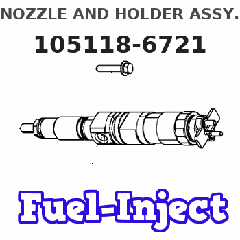
Information nozzle and holder assy.
BOSCH
9 430 613 696
9430613696
ZEXEL
105118-6721
1051186721
ISUZU
8972112800
8972112800
Rating:
Compare Prices: .
As an associate, we earn commssions on qualifying purchases through the links below

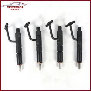
4PCS Fuel Injector 105118-6721 48-3230T1 Suitable for Isuzu Engine 4JG1 4JG2
TuneCrumph Part Name:Fuel Injector || Part Number:105118-6721 48-3230T1 || Application:Suitable for Isuzu Engine 4JG1 4JG2 || Attention: Dear buyers, precise matching of auto parts is the prerequisite for safe installation! To avoid the problems such as returns, exchanges or installation hazards caused by incorrect model selection, please carefully read and verify the model before placing your order. Thank you for your support! || NOTE:We are fully aware that your satisfaction is the driving force for the growth of our brand. Thank you for giving us the opportunity to serve you. If there is anything we haven't covered, please give us your feedback directly. Your suggestions are extremely precious to us!
TuneCrumph Part Name:Fuel Injector || Part Number:105118-6721 48-3230T1 || Application:Suitable for Isuzu Engine 4JG1 4JG2 || Attention: Dear buyers, precise matching of auto parts is the prerequisite for safe installation! To avoid the problems such as returns, exchanges or installation hazards caused by incorrect model selection, please carefully read and verify the model before placing your order. Thank you for your support! || NOTE:We are fully aware that your satisfaction is the driving force for the growth of our brand. Thank you for giving us the opportunity to serve you. If there is anything we haven't covered, please give us your feedback directly. Your suggestions are extremely precious to us!

4 Pieces Fuel Injector 105118-6721 for Isuzu Engine 4JG1 4JG2 4JG1-S
DIGERTECH Part number:105118-6721 || Application:for Isuzu Engine 4JG1 4JG2 4JG1-S
DIGERTECH Part number:105118-6721 || Application:for Isuzu Engine 4JG1 4JG2 4JG1-S

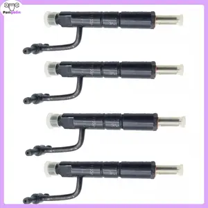
4JG1 4JG2 Engine Isuzu fits for Fuel Injector 105118-6721 48-3230T1 4PCS
KoovDem Part Number: 105118-6721 48-3230T1 || Part Name:Fuel Injectors || Quality Assurance: Each injector undergoes factory testing for flow rate, pressure retention and leak prevention || Compatibility Guarantee: Matches original equipment specifications for seamless performance integration || Please verify your required part number before ordering. You may also provide your vehicle details for our compatibility verification service.
KoovDem Part Number: 105118-6721 48-3230T1 || Part Name:Fuel Injectors || Quality Assurance: Each injector undergoes factory testing for flow rate, pressure retention and leak prevention || Compatibility Guarantee: Matches original equipment specifications for seamless performance integration || Please verify your required part number before ordering. You may also provide your vehicle details for our compatibility verification service.
You can express buy:
USD 114.46
14-06-2025
14-06-2025
Fuel Injector 8972112800 8972112801 For Isuzu Engine 4JG1 4JG2 4JG1-S CC4JG1-PH02

USD 88.17
19-05-2025
19-05-2025
4 Pcs Fuel Injector 8972112800 8972112801 For Isuzu 4JG1 4JG2 CC4JG1-PH02 Engine Hitachi New Holland John Deere Excavator Parts
USD 170.33
29-04-2025
29-04-2025
4Pcs 8972112801 Fuel Injector For Isuzu 4JG1 Engine 8972112800 New Car Accessories
Images:
USD 172.87

[28-Apr-2025]
Include in #1:
101402-7730
as NOZZLE AND HOLDER ASSY
Cross reference number
Zexel num
Bosch num
Firm num
Name
105118-6721
8972112800 ISUZU
NOZZLE AND HOLDER ASSY.
4JG1-S K 53KF NOZZLE & HOLDER ASSY N&NH KBALP N&NH
4JG1-S K 53KF NOZZLE & HOLDER ASSY N&NH KBALP N&NH
Information:
Start By:a. remove oil panb. remove oil pump 1. Remove bolts (1) and bearing cap (2). Remove the bearing half from the cap.
If the crankshaft is turned in the wrong direction, the tab of the bearing will be pushed between the crankshaft and cylinder block. This can cause damage to either or both the crankshaft and the block.
2. Remove the upper half of the main bearings as follows:a. Turn the crankshaft until tool (A) can be installed in the crankshaft journal oil passage. Install tool (A).b. Turn the crankshaft in the direction which will push the upper main bearing out, tab end first.c. Check the condition of the bearings. (See Guideline For Reusable Parts, Main And Connecting Rod Bearings, FORM No. SEBF8009 and SEBD0531). Both the center and two end main journals have no oil hole. To remove these bearings, put a thin piece of soft material, (that will not damage the crankshaft journal), against the end of the bearing opposite the tab. Hit the bearing with the soft material until the tab of the bearing is free from the groove in the block. The following steps are for the installation of the crankshaft main bearings. Put clean engine oil on the main bearings for the assembly. Also, be sure the tabs on the back side of the main bearings fit in the grooves of the main bearing caps and cylinder block.3. Clean the surfaces in the cylinder block for the main bearings. Use tool (A), and install new upper halves of main bearing (bearings with the oil hole) in the cylinder block. Do not put oil on the back of the bearing.4. Clean the surface of the main bearing caps for the main bearings. Install the new lower halves of the main bearings in the main caps. Do not put oil on the back of the bearing.
Install the main bearing caps with the sequence number to the right, 1 through 7, front to rear.
5. Put main bearing caps (2) in position on the cylinder block. Put engine oil on the bolt threads and the contact surfaces of the bolt heads, and install the bolts. Tighten the bolts on the side where the main bearing tabs are located to a torque of 54 7 N m (40 5 lb.ft.). Tighten the bolts on the opposite side to a torque of 54 7 N m (40 5 lb.ft.).6. Put a mark on each bolt head and the bearing caps. Turn the bolts that are opposite the main bearing tabs an additional 90° 5° turn. Then turn the bolts on the side where the main bearing tabs are located an additional 90° 5° turn. 8. Check the end play of the crankshaft with a dial indicator and magnetic base. The end play must be 0.07 to 0.24 mm (.003 to .009 in.). The end play is controlled by the thrust bearings, which are part of main bearing No. six.End By:a. install oil pumpb. install oil pan