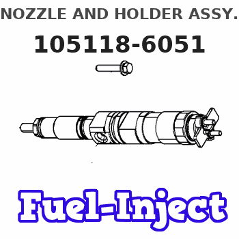
Information nozzle and holder assy.
BOSCH
9 430 610 152
9430610152
ZEXEL
105118-6051
1051186051
ISUZU
8971198120
8971198120

Rating:
Compare Prices: .
As an associate, we earn commssions on qualifying purchases through the links below
4 PCS Fuel Injector 8971198120 8-97119812-0 for Isuzu 4HF1 NKR NQR
DIGERTECH Part number:8971198120 || Application:for Isuzu 4HF1 NKR NQR
DIGERTECH Part number:8971198120 || Application:for Isuzu 4HF1 NKR NQR
4Pcs Fuel Injection 8971198120 For Isuzu Engine 4HF1 Truck NKR NQR
oiasdfhjdg Product name:Fuel Injection || Part Number:8971198120 || APPlication:For Isuzu Engine 4HF1 Truck NKR NQR || 1.Please ensure to provide us with the correct, accurate, and detailed delivery address and contact information. || 2.Please carefully compare the OE numbers before purchasing the product to match your original parts and avoid wasting your valuable time.
oiasdfhjdg Product name:Fuel Injection || Part Number:8971198120 || APPlication:For Isuzu Engine 4HF1 Truck NKR NQR || 1.Please ensure to provide us with the correct, accurate, and detailed delivery address and contact information. || 2.Please carefully compare the OE numbers before purchasing the product to match your original parts and avoid wasting your valuable time.
Heavy Equipment Parts & Accessories – Durable High-Performance Replacement Parts 4X Fuel Injector 8-97119812-0 8971198120 for Isuzu 4HF1 NKR NQR Model-Z59-FX5697
Generic ✔ Premium Quality & Durability – Manufactured with high-grade materials to ensure long-lasting performance in demanding industrial and construction environments. || ✔ Wide Compatibility – Designed to fit various heavy equipment brands and models, including excavators, loaders, bulldozers, and more for seamless installation. || ✔ Enhanced Performance & Efficiency – Engineered to withstand extreme conditions, reducing downtime and increasing the lifespan of your machinery. || ✔ Easy Installation & Maintenance – Precise fitment and hassle-free setup make replacements quick and efficient, saving time and labor costs. || ✔ Reliable Supplier – Sourced from trusted manufacturers with strict quality control standards, ensuring timely superior product reliability.
Generic ✔ Premium Quality & Durability – Manufactured with high-grade materials to ensure long-lasting performance in demanding industrial and construction environments. || ✔ Wide Compatibility – Designed to fit various heavy equipment brands and models, including excavators, loaders, bulldozers, and more for seamless installation. || ✔ Enhanced Performance & Efficiency – Engineered to withstand extreme conditions, reducing downtime and increasing the lifespan of your machinery. || ✔ Easy Installation & Maintenance – Precise fitment and hassle-free setup make replacements quick and efficient, saving time and labor costs. || ✔ Reliable Supplier – Sourced from trusted manufacturers with strict quality control standards, ensuring timely superior product reliability.
You can express buy:
USD 52.09
14-06-2025
14-06-2025
For ISUZU NPR NQR 4HF1 4HG1 8971198120 Fuel Injector Nozzle Tip DLLA154PN186 105017-1860
Include in #1:
101401-4991
as NOZZLE AND HOLDER ASSY
Cross reference number
Information:
1. Install the turbocharger on tool (A) as shown.2. Put alignment marks on three housings of the turbocharger for correct alignment during assembly. Loosen clamp (2), and remove the clamp and housing (1) from housing assembly (3). 3. Loosen clamp (4), and remove housing assembly (3) from housing (5). 4. Put the cartridge group in position in tool (B) as shown.
When the nut is loosened, do not put a side force on the shaft. This can result in a bent shaft.
5. Use a 5S9566 Sliding T-Wrench and a universal socket (6) to remove the nut that holds the compressor wheel to the wheel assembly.6. Remove compressor wheel (7) and the shims from wheel assembly (8).7. Remove housing assembly (3) from wheel assembly (8). 8. Remove ring (9) and backplate (10) from wheel assembly (8). 9. Use tool (C), and remove snap ring (11) from housing assembly (3). 10. Remove insert (12) and sleeve (13) from housing assembly (3). 11. Remove ring (14) from sleeve (13). 12. Remove two screws (15) and deflector (16) from housing assembly (3). 13. Remove ring (18) and bearing assembly (17) from the housing assembly. 14. Remove sleeve (19) and ring (20) from the housing assembly. 15. Remove O-ring seal (23) from the housing assembly.16. Use tool (D), and remove snap ring (22) from the housing assembly.17. Remove bearing (21). Remove the snap ring behind the bearing with tool (D). 18. Use tool (D), and remove snap ring (25) from the housing assembly.19. Remove bearing (24). Remove the snap ring behind the bearing with tool (D).20. Check all the parts of the turbocharger for damage. If the parts are damaged, use new parts for replacement. See Special Instruction, Form No. SMHS6854 for Turbocharger Reconditioning. Also see Guidelines For Reusable Parts, Form No. SEBF8018.Assemble Turbocharger (S4A)
1. Make sure that all of the oil passages in the turbocharger cartridge housing are clean and free of dirt and foreign material. Do not put oil on any parts of the turbocharger until after the compressor wheel has been installed. After the turbocharger has been assembled, pour clean engine oil into the oil inlet of the turbocharger.
Make sure that the snap rings that hold bearings (2) and (5) in position in housing assembly (3) are installed with the round edge of the outside diameter toward the bearing.
2. Install the snap ring behind bearing (2) with tool (A).3. Install bearing (2) in housing assembly (3).4. Use tool (A), and install snap ring (1) in the housing assembly. 5. Install the snap ring behind bearing (5) with tool (A).6. Install bearing (5) in the housing assembly.7. Use tool (A), and install snap ring (4) in the housing assembly. 8. Put wheel assembly (8) in position on tool (B) as shown.9. Put backplate (7) in position on the wheel assembly. Put 6V2055 High Vacuum Grease


