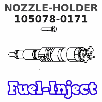
Information nozzle-holder
BOSCH
9 430 615 190
9430615190
ZEXEL
105078-0171
1050780171
ISUZU
8970908421
8970908421
Rating:
Scheme ###:
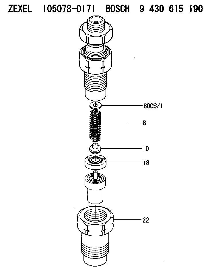
| 8. | [1] | 150562-4700 | COMPRESSION SPRING |
| 10. | [1] | 150560-0201 | SLOTTED WASHER |
| 18. | [1] | 150524-5300 | SPACER BUSHING |
| 22. | [1] | 150655-1500 | NOZZLE-RETAINING NUT |
| 800S/1. | [0] | 150534-2600 | SHIM T0.1 |
| 800S/1. | [0] | 150534-2700 | SHIM T0.2 |
| 800S/1. | [0] | 150534-2800 | SHIM T0.3 |
| 800S/1. | [0] | 150534-2900 | SHIM T0.4 |
| 800S/1. | [0] | 150534-3000 | SHIM T0.5 |
| 800S/1. | [0] | 150534-3100 | SHIM T0.52 |
| 800S/1. | [0] | 150534-3200 | SHIM T0.54 |
| 800S/1. | [0] | 150534-3300 | SHIM T0.56 |
| 800S/1. | [0] | 150534-3400 | SHIM T0.58 |
| 800S/1. | [0] | 150534-3500 | SHIM T0.8 |
Cross reference number
Zexel num
Bosch num
Firm num
Name
105078-0171
9 430 615 190
8970908421 ISUZU
NOZZLE-HOLDER
K 53LZ NOZZLE HOLDER NH NH
K 53LZ NOZZLE HOLDER NH NH
Information:
Rubber Damper (If Equipped)
The vibration damper can have a visual wobble (movement to the front and rear when in rotation) on the outer ring. This does not mean a replacement is necessary since some wobble of the outer ring is normal. To see if the amount of wobble is acceptable, or replacement is necessary, check the damper with the procedure in the Testing and Adjusting section of the Service Manual.The vibration damper has marks on the hub (1) and ring (2). These marks will indicate the condition of the vibration damper. If the marks are not in alignment, the rubber seal (3) between the ring and the hub has separated from the ring and/or hub. If the marks are not in alignment, install a new vibration damper. Refer to the Service Manual for the necessary replacement procedure.Air Compressor
Inspect/Check
Do not disconnect the air line from the air compressor governor without purging the air brake and auxiliary air systems.Failure to purge the air brake and auxiliary air systems before removing the air compressor could cause personal injury.
Inspect the air compressor as instructed by the OEM truck manufacturers' instructions or for more information on how to check your air compressor, refer to the Service Manual for this engine.If you decide to inspect your air compressor, be sure to observe the following actions. Visually check for fluid leaks and listen for air leaks. Release the air pressure in the air tank until the air pressure is zero. Remove discharge fittings and inspect compressor discharge port and discharge line for excessive carbon deposits. The discharge line must be cleaned or replaced and the compressor checked more thoroughly if there is excessive carbon build-up in either the discharge line or compressor discharge port.For more information on how to check your air compressor, refer to the OEM truck manufacturer's instructions or engine Service Manual.Engine Valve Lash
The procedures for engine valve lash should be performed according to the information in the Service Manual.
Check/Adjust
Be sure the engine cannot be started while this maintenance is being performed. To prevent possible injury, do not use the starting motor to turn the flywheel.Hot engine components can cause burns. Allow additional time for the engine to cool before measuring/adjusting valve lash.
Adjust the valve lash to the setting given in the chart above.Refer to the Service Manual or your Caterpillar dealer for the complete valve adjustment procedure.Bridge Adjustment
The valve bridge should be checked and/or adjusted each time valve lash is checked and/or adjusted. Valve and valve mechanism components do not always wear evenly which can allow the bridge to be out of adjustment.It is not necessary to remove the rocker arm shaft to adjust the valve bridges, but there must be clearance.Engine Valve Rotators
When inspecting the valve rotators, protective glasses or face shield and protective clothing must be worn, to prevent being burned by hot oil or spray.
Observe rotation of valves with engine idling after setting the valve lash. Caterpillar recommends replacement of improperly operating valve rotators. An improperly operating valve rotator
Have questions with 105078-0171?
Group cross 105078-0171 ZEXEL
Mazda
Isuzu
105078-0171
9 430 615 190
8970908421
NOZZLE-HOLDER