Information nozzle-holder
BOSCH
9 430 615 058
9430615058
ZEXEL
105048-3060
1050483060
KOMATSU
6207113110
6207113110

Rating:
Compare Prices: .
As an associate, we earn commssions on qualifying purchases through the links below

MWENJIAN Diesel Fuel Injector 6207-11-3100 6207113100 6207113110 105048-3060 Compatible for Komatsu 4D95 6D95 Engine Nozzle(105048-3060)
MWENJIAN Replaces Part Number: 6207-11-3100 6207113100 6207113110 105048-3060 || Our injector nozzle is crafted from a robust combination of metal and composite plastic, ensuring increased durability and resistance to cracking for long-lasting performance in your vehicle. || This injector nozzle features excellent fuel atomization and a tightly controlled injection pattern, allowing for better fuel evaporation, which ultimately leads to improved engine efficiency and reduced emissions. || An internal seal ring is included to prevent fuel exposure and minimize stickiness during operation, ensuring a longer lifespan and reliable performance of your injector nozzle. || The injector nozzle is designed with a 2-pin count, making it compatible with various vehicle models and easy to install as a direct replacement part.
MWENJIAN Replaces Part Number: 6207-11-3100 6207113100 6207113110 105048-3060 || Our injector nozzle is crafted from a robust combination of metal and composite plastic, ensuring increased durability and resistance to cracking for long-lasting performance in your vehicle. || This injector nozzle features excellent fuel atomization and a tightly controlled injection pattern, allowing for better fuel evaporation, which ultimately leads to improved engine efficiency and reduced emissions. || An internal seal ring is included to prevent fuel exposure and minimize stickiness during operation, ensuring a longer lifespan and reliable performance of your injector nozzle. || The injector nozzle is designed with a 2-pin count, making it compatible with various vehicle models and easy to install as a direct replacement part.

£131.59
14 Mar 2018
Bosch: Bosch
Bosch 9430615058 Nozzle-Holder Assembly
Scheme ###:
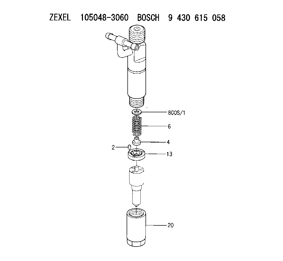
| 2. | [2] | 150508-5900 | BEARING PIN |
| 4. | [1] | 150515-9900 | SLOTTED WASHER |
| 6. | [1] | 150562-4300 | COMPRESSION SPRING |
| 13. | [1] | 150524-4600 | SPACER BUSHING |
| 20. | [1] | 150655-0000 | NOZZLE-RETAINING NUT |
| 800S/1. | [1] | 150591-1000 | SHIM D7.2&3.6T0.10 |
| 800S/1. | [1] | 150591-2000 | SHIM D7.2&3.6T0.20 |
| 800S/1. | [1] | 150591-3000 | SHIM D7.2&3.6T0.30 |
| 800S/1. | [1] | 150591-4000 | SHIM D7.2&3.6T0.40 |
| 800S/1. | [1] | 150591-5000 | SHIM D7.2&3.6T0.50 |
| 800S/1. | [1] | 150591-5100 | SHIM D7.2&3.6T0.51 |
| 800S/1. | [1] | 150591-5200 | SHIM D7.2&3.6T0.52 |
| 800S/1. | [1] | 150591-5300 | SHIM D7.2&3.6T0.53 |
| 800S/1. | [1] | 150591-5400 | SHIM D7.2&3.6T0.54 |
| 800S/1. | [1] | 150591-5500 | SHIM D7.2&3.6T0.55 |
| 800S/1. | [1] | 150591-5600 | SHIM D7.2&3.6T0.56 |
| 800S/1. | [1] | 150591-5700 | SHIM D7.2&3.6T0.57 |
| 800S/1. | [1] | 150591-5800 | SHIM D7.2&3.6T0.58 |
| 800S/1. | [1] | 150591-5900 | SHIM D7.2&3.6T0.59 |
Include in #1:
101491-9357
as NOZZLE-HOLDER
Cross reference number
Zexel num
Bosch num
Firm num
Name
105048-3060
9 430 615 058
6207113110 KOMATSU
NOZZLE-HOLDER
K 53LZ NOZZLE HOLDER NH NH
K 53LZ NOZZLE HOLDER NH NH
105048-3060
9 430 615 058
6207113060 KOMATSU
NOZZLE-HOLDER
A K 53LZ NOZZLE HOLDER NH NH
A K 53LZ NOZZLE HOLDER NH NH
Information:
Start By:a. remove oil pumpb. remove oil pan plate
Keep all parts clean from contaminants. Contaminants put into the system may cause rapid wear and shortened component life.
1. Turn the crankshaft until two pistons are at the bottom center. Remove connecting rod caps (1) from the two connecting rods. Remove the lower half of the rod bearing from the rod bearing cap.
The connecting rod bolts are loose on the connecting rods and can fall out when the nuts are removed.
2. Push the connecting rods away from the crankshaft. Remove the upper half of the rod bearing from the connecting rod. Install the connecting rod bearings dry when the clearance checks are made. Put clean engine oil on the connecting rod bearings for final assembly.3. Install the upper half of the rod bearing in the connecting rod.4. Install the lower half of the rod bearing in the connecting rod cap. Be sure the tabs in the back of the connecting rod bearings are in the tab grooves of the connecting rod and cap. 5. Use Plastigage (A) to check the connecting rod bearing clearance.6. Put Plastigage (A) on the connecting rod bearing.7. Put 2P2506 Thread Lubricant on the threads of the rod bolts and seat surfaces of the nuts.
When connecting rod caps are installed, make sure the number on the side of the cap is next to and respective with the number on the side of the connecting rod.
Do not turn the crankshaft when Plastigage (A) is in position.
Do not use an impact wrench to tighten the nuts the additional 90°.
8. Install connecting rod cap (1). Install the nuts. Tighten the nuts to a torque of 40 4 N m (30 3 lb ft) Put a mark on each nut and the end of each bolt. Tighten the nuts 90° more. Remove the connecting rod caps. Remove Plastigage (A) and measure the width of the Plastigage. The connecting rod clearance must be 0.076 to 0.168 mm (.0030 to .0066 in) for new bearings. The maximum clearance with used bearings is 0.25 mm (.010 in).9. Install the connecting rod caps and tighten the nuts as in Step 8.10. Do Steps 1 through 9 for the remainder of the connecting rod bearings.End By:a. install oil pan plateb. install oil pump
Perform Scheduled Oil Sampling on oil wetted compartments after performing service work to check for contaminants left in the system following repair. Contaminants put into the system may cause rapid wear and shortened component life.
Have questions with 105048-3060?
Group cross 105048-3060 ZEXEL
Mitsubishi
Isuzu
Mitsubishi
Mazda
Komatsu
105048-3060
9 430 615 058
6207113110
NOZZLE-HOLDER
105048-3060
9 430 615 058
6207113060
NOZZLE-HOLDER