Information nozzle-holder
BOSCH
9 430 615 342
9430615342
ZEXEL
105041-5050
1050415050
HINO
236201560A
236201560a
Rating:
Scheme ###:
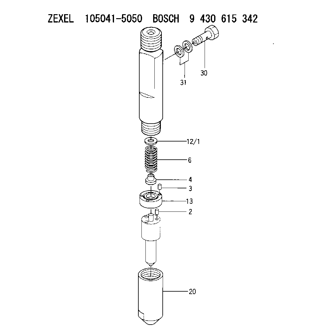
| 2. | [2] | 150508-3300 | BEARING PIN |
| 3. | [2] | 150525-1701 | BEARING PIN |
| 4. | [1] | 150550-4700 | STOP PIN |
| 6. | [1] | 150562-1700 | COMPRESSION SPRING |
| 12/1. | [1] | 150530-4000 | SHIM D10.3&4.5T0.5 |
| 12/1. | [1] | 150530-4100 | SHIM D10.3&4.5T0.525 |
| 12/1. | [1] | 150530-4200 | SHIM D10.3&4.5T0.55 |
| 12/1. | [1] | 150530-4300 | SHIM D10.3&4.5T0.575 |
| 12/1. | [1] | 150530-4400 | SHIM D10.3&4.5T0.6 |
| 12/1. | [1] | 150530-4500 | SHIM D10.3&4.5T0.625 |
| 12/1. | [1] | 150530-4600 | SHIM D10.3&4.5T0.65 |
| 12/1. | [1] | 150530-4700 | SHIM D10.3&4.5T0.675 |
| 12/1. | [1] | 150530-4800 | SHIM D10.3&4.5T0.7 |
| 12/1. | [1] | 150530-4900 | SHIM D10.3&4.5T0.725 |
| 12/1. | [1] | 150530-5000 | SHIM D10.3&4.5T0.75 |
| 12/1. | [1] | 150530-5100 | SHIM D10.3&4.5T0.775 |
| 12/1. | [1] | 150530-5200 | SHIM D10.3&4.5T0.8 |
| 12/1. | [1] | 150530-5300 | SHIM D10.3&4.5T0.825 |
| 12/1. | [1] | 150530-5400 | SHIM D10.3&4.5T0.85 |
| 12/1. | [1] | 150530-5500 | SHIM D10.3&4.5T0.875 |
| 12/1. | [1] | 150530-5600 | SHIM D10.3&4.5T0.9 |
| 12/1. | [1] | 150530-5700 | SHIM D10.3&4.5T0.925 |
| 12/1. | [1] | 150530-5800 | SHIM D10.3&4.5T0.95 |
| 12/1. | [1] | 150530-5900 | SHIM D10.3&4.5T0.975 |
| 12/1. | [1] | 150530-6000 | SHIM D10.3&4.5T1.0 |
| 12/1. | [1] | 150530-6100 | SHIM D10.3&4.5T1.025 |
| 12/1. | [1] | 150530-6200 | SHIM D10.3&4.5T1.05 |
| 12/1. | [1] | 150530-6300 | SHIM D10.3&4.5T1.075 |
| 12/1. | [1] | 150530-6400 | SHIM D10.3&4.5T1.1 |
| 12/1. | [1] | 150530-6500 | SHIM D10.3&4.5T1.125 |
| 12/1. | [1] | 150530-6600 | SHIM D10.3&4.5T1.15 |
| 12/1. | [1] | 150530-6700 | SHIM D10.3&4.5T1.175 |
| 12/1. | [1] | 150530-6800 | SHIM D10.3&4.5T1.2 |
| 12/1. | [1] | 150530-6900 | SHIM D10.3&4.5T1.225 |
| 12/1. | [1] | 150530-7000 | SHIM D10.3&4.5T1.25 |
| 12/1. | [1] | 150530-7100 | SHIM D10.3&4.5T1.275 |
| 12/1. | [1] | 150530-7200 | SHIM D10.3&4.5T1.3 |
| 12/1. | [1] | 150530-7300 | SHIM D10.3&4.5T1.325 |
| 12/1. | [1] | 150530-7400 | SHIM D10.3&4.5T1.35 |
| 12/1. | [1] | 150530-7500 | SHIM D10.3&4.5T1.375 |
| 12/1. | [1] | 150530-7600 | SHIM D10.3&4.5T1.4 |
| 12/1. | [1] | 150530-7700 | SHIM D10.3&4.5T1.425 |
| 12/1. | [1] | 150530-7800 | SHIM D10.3&4.5T1.45 |
| 12/1. | [1] | 150530-7900 | SHIM D10.3&4.5T1.475 |
| 12/1. | [1] | 150530-8000 | SHIM D10.3&4.5T1.5 |
| 12/1. | [1] | 150530-8100 | SHIM D10.3&4.5T1.525 |
| 12/1. | [1] | 150530-8200 | SHIM D10.3&4.5T1.55 |
| 12/1. | [1] | 150530-8300 | SHIM D10.3&4.5T1.575 |
| 12/1. | [1] | 150530-8400 | SHIM D10.3&4.5T1.6 |
| 12/1. | [1] | 150530-8500 | SHIM D10.3&4.5T1.625 |
| 12/1. | [1] | 150530-8600 | SHIM D10.3&4.5T1.65 |
| 12/1. | [1] | 150530-8700 | SHIM D10.3&4.5T1.675 |
| 12/1. | [1] | 150530-8800 | SHIM D10.3&4.5T1.7 |
| 12/1. | [1] | 150530-8900 | SHIM D10.3&4.5T1.725 |
| 12/1. | [1] | 150530-9000 | SHIM D10.3&4.5T1.75 |
| 12/1. | [1] | 150530-9100 | SHIM D10.3&4.5T1.775 |
| 12/1. | [1] | 150530-9200 | SHIM D10.3&4.5T1.8 |
| 12/1. | [1] | 150530-9300 | SHIM D10.3&4.5T1.825 |
| 12/1. | [1] | 150530-9400 | SHIM D10.3&4.5T1.85 |
| 12/1. | [1] | 150530-9500 | SHIM D10.3&4.5T1.875 |
| 12/1. | [1] | 150530-9600 | SHIM D10.3&4.5T1.9 |
| 12/1. | [1] | 150530-9700 | SHIM D10.3&4.5T1.925 |
| 12/1. | [1] | 150530-9800 | SHIM D10.3&4.5T1.95 |
| 12/1. | [1] | 150530-9900 | SHIM D10.3&4.5T1.975 |
| 13. | [1] | 150524-4300 | SPACER BUSHING |
| 20. | [1] | 150650-7900 | NOZZLE-RETAINING NUT |
| 30. | [1] | 150613-2000 | EYE BOLT |
| 31. | [2] | 150623-6500 | GASKET |
Include in #1:
101402-2001
as NOZZLE-HOLDER
Cross reference number
Zexel num
Bosch num
Firm num
Name
105041-5050
9 430 615 342
236201560A HINO
NOZZLE-HOLDER
K 53LZ NOZZLE HOLDER NH NH
K 53LZ NOZZLE HOLDER NH NH
Information:
Take special care when working around an engine if it is running.
9S9102 THERMISTOR THERMOMETER GROUP INSTALLEDStart the engine. Cover the radiator to reduce air flow and cooling. The instrument panel temperature gauge should register a comparable temperature to that indicated by the 9S9102 Thermistor Thermometer Group.Pressure Cap
If the pressure check indicates that the system is unable to hold pressure, the source of the pressure leak must be determined. One of the causes of cooling system pressure loss can be a faulty pressure cap seal. Inspect the pressure cap carefully for possible damage to the seal or sealing surfaces. The build-up of deposits on the cap, seal and filler neck should be removed.Water Temperature Regulator (Thermostat)
The opening temperature of thermostats (bench test in atmospheric pressure) should be as listed in the following charts. 1. Remove the thermostats from the front cover.2. Suspend the thermostats and a thermometer in a pan of water.3. Apply heat to the pan and stir the water to maintain uniformity.4. Observe the opening temperature of the thermostats.If a thermostat does not operate correctly, install a new thermostat.Water Pump Pressure Check
9S8138 Pressure Gauge3B7722 BushingThe pressure at the water pump outlet determines if the shunt system and water pump are operating properly. To check the pump pressure install the pressure gauge (2) in the front cover as shown. The pressure should be a minimum of 15 psi (1.05 kg/cm2) at 2800 rpm on all engines.
GAUGE INSTALLED
1. 3B7722 Bushing. 2. 9S8138 Pressure Gauge.If pump pressure does not meet the minimum pressure: First, check the vent tube between the radiator top tank and the expansion tank; it should have an inside diameter of approximately .19 in. (4.8 mm). Second, check to see that the shunt line has a minimum inside diameter of .75 in. (19.1 mm).Inspect Rebuilt Water Pumps
Individual parts for the water pump are not serviced. However, some firms may be rebuilding these pumps, using a different impeller, or one which they have machined on the seal face or on the vanes.Unless the same impeller or one identical to it is used and positioned on the shaft within the specifications, a rebuilt pump may not produce sufficient water flow for adequate cooling. If the rebuilder used an impeller design different from the original equipment pump, he should be asked to guarantee that his rebuilt pump output meets new pump requirements.Here is how to check a rebuilt pump:1. Bearing end clearance should be .001 to .025 in. (0.03 to 0.64 mm).2. The clearance (2) between the impeller face and the front cover is .005 to .045 in. (0.13 to 1.14 mm).This clearance indicates the condition of the impeller and its location on the shaft. The bearing and front cover condition are also indicated. Check impeller clearance as follows:
IMPELLER CLEARANCE AND HEIGHT
1. Front cover. 2. Impeller clearance. 3. Impeller. 4. Impeller height [1.370 to 1.400 (34.80 to 35.60 mm)].a. Place a small ball of clay or wax on two impeller vanes directly opposite each other.b. Using a new gasket, install
Have questions with 105041-5050?
Group cross 105041-5050 ZEXEL
Kubota
Hino
Hino
105041-5050
9 430 615 342
236201560A
NOZZLE-HOLDER