Information nozzle-holder
BOSCH
9 430 615 071
9430615071
ZEXEL
105041-5041
1050415041
HINO
236201570A
236201570a

Rating:
Compare Prices: .
As an associate, we earn commssions on qualifying purchases through the links below

$175.84
11 Nov 2019
-: -
Bosch 9430615071 Nozzle-Holder Assembly
Scheme ###:
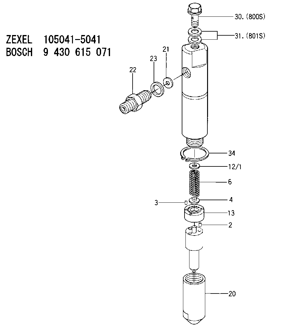
| 2. | [2] | 150508-3300 | BEARING PIN |
| 3. | [2] | 150525-1701 | BEARING PIN |
| 4. | [1] | 150550-4700 | STOP PIN |
| 6. | [1] | 150562-1700 | COMPRESSION SPRING |
| 12/1. | [1] | 150530-4000 | SHIM D10.3&4.5T0.5 |
| 12/1. | [1] | 150530-4100 | SHIM D10.3&4.5T0.525 |
| 12/1. | [1] | 150530-4200 | SHIM D10.3&4.5T0.55 |
| 12/1. | [1] | 150530-4300 | SHIM D10.3&4.5T0.575 |
| 12/1. | [1] | 150530-4400 | SHIM D10.3&4.5T0.6 |
| 12/1. | [1] | 150530-4500 | SHIM D10.3&4.5T0.625 |
| 12/1. | [1] | 150530-4600 | SHIM D10.3&4.5T0.65 |
| 12/1. | [1] | 150530-4700 | SHIM D10.3&4.5T0.675 |
| 12/1. | [1] | 150530-4800 | SHIM D10.3&4.5T0.7 |
| 12/1. | [1] | 150530-4900 | SHIM D10.3&4.5T0.725 |
| 12/1. | [1] | 150530-5000 | SHIM D10.3&4.5T0.75 |
| 12/1. | [1] | 150530-5100 | SHIM D10.3&4.5T0.775 |
| 12/1. | [1] | 150530-5200 | SHIM D10.3&4.5T0.8 |
| 12/1. | [1] | 150530-5300 | SHIM D10.3&4.5T0.825 |
| 12/1. | [1] | 150530-5400 | SHIM D10.3&4.5T0.85 |
| 12/1. | [1] | 150530-5500 | SHIM D10.3&4.5T0.875 |
| 12/1. | [1] | 150530-5600 | SHIM D10.3&4.5T0.9 |
| 12/1. | [1] | 150530-5700 | SHIM D10.3&4.5T0.925 |
| 12/1. | [1] | 150530-5800 | SHIM D10.3&4.5T0.95 |
| 12/1. | [1] | 150530-5900 | SHIM D10.3&4.5T0.975 |
| 12/1. | [1] | 150530-6000 | SHIM D10.3&4.5T1.0 |
| 12/1. | [1] | 150530-6100 | SHIM D10.3&4.5T1.025 |
| 12/1. | [1] | 150530-6200 | SHIM D10.3&4.5T1.05 |
| 12/1. | [1] | 150530-6300 | SHIM D10.3&4.5T1.075 |
| 12/1. | [1] | 150530-6400 | SHIM D10.3&4.5T1.1 |
| 12/1. | [1] | 150530-6500 | SHIM D10.3&4.5T1.125 |
| 12/1. | [1] | 150530-6600 | SHIM D10.3&4.5T1.15 |
| 12/1. | [1] | 150530-6700 | SHIM D10.3&4.5T1.175 |
| 12/1. | [1] | 150530-6800 | SHIM D10.3&4.5T1.2 |
| 12/1. | [1] | 150530-6900 | SHIM D10.3&4.5T1.225 |
| 12/1. | [1] | 150530-7000 | SHIM D10.3&4.5T1.25 |
| 12/1. | [1] | 150530-7100 | SHIM D10.3&4.5T1.275 |
| 12/1. | [1] | 150530-7200 | SHIM D10.3&4.5T1.3 |
| 12/1. | [1] | 150530-7300 | SHIM D10.3&4.5T1.325 |
| 12/1. | [1] | 150530-7400 | SHIM D10.3&4.5T1.35 |
| 12/1. | [1] | 150530-7500 | SHIM D10.3&4.5T1.375 |
| 12/1. | [1] | 150530-7600 | SHIM D10.3&4.5T1.4 |
| 12/1. | [1] | 150530-7700 | SHIM D10.3&4.5T1.425 |
| 12/1. | [1] | 150530-7800 | SHIM D10.3&4.5T1.45 |
| 12/1. | [1] | 150530-7900 | SHIM D10.3&4.5T1.475 |
| 12/1. | [1] | 150530-8000 | SHIM D10.3&4.5T1.5 |
| 12/1. | [1] | 150530-8100 | SHIM D10.3&4.5T1.525 |
| 12/1. | [1] | 150530-8200 | SHIM D10.3&4.5T1.55 |
| 12/1. | [1] | 150530-8300 | SHIM D10.3&4.5T1.575 |
| 12/1. | [1] | 150530-8400 | SHIM D10.3&4.5T1.6 |
| 12/1. | [1] | 150530-8500 | SHIM D10.3&4.5T1.625 |
| 12/1. | [1] | 150530-8600 | SHIM D10.3&4.5T1.65 |
| 12/1. | [1] | 150530-8700 | SHIM D10.3&4.5T1.675 |
| 12/1. | [1] | 150530-8800 | SHIM D10.3&4.5T1.7 |
| 12/1. | [1] | 150530-8900 | SHIM D10.3&4.5T1.725 |
| 12/1. | [1] | 150530-9000 | SHIM D10.3&4.5T1.75 |
| 12/1. | [1] | 150530-9100 | SHIM D10.3&4.5T1.775 |
| 12/1. | [1] | 150530-9200 | SHIM D10.3&4.5T1.8 |
| 12/1. | [1] | 150530-9300 | SHIM D10.3&4.5T1.825 |
| 12/1. | [1] | 150530-9400 | SHIM D10.3&4.5T1.85 |
| 12/1. | [1] | 150530-9500 | SHIM D10.3&4.5T1.875 |
| 12/1. | [1] | 150530-9600 | SHIM D10.3&4.5T1.9 |
| 12/1. | [1] | 150530-9700 | SHIM D10.3&4.5T1.925 |
| 12/1. | [1] | 150530-9800 | SHIM D10.3&4.5T1.95 |
| 12/1. | [1] | 150530-9900 | SHIM D10.3&4.5T1.975 |
| 13. | [1] | 150524-4300 | SPACER BUSHING |
| 20. | [1] | 150650-7900 | NOZZLE-RETAINING NUT |
| 21. | [1] | 029300-3100 | GASKET |
| 22. | [1] | 150645-7300 | INLET UNION |
| 23. | [1] | 150619-0500 | SEAL RING |
| 30. | [1] | 150613-1801 | EYE BOLT |
| 31. | [2] | 150623-6400 | GASKET |
| 34. | [1] | 150640-3900 | LOCKING WASHER |
| 800S. | [1] | 150613-1801 | EYE BOLT |
| 801S. | [2] | 150623-6400 | GASKET |
Include in #1:
101401-2013
as NOZZLE-HOLDER
Cross reference number
Zexel num
Bosch num
Firm num
Name
105041-5041
9 430 615 071
236201570A HINO
NOZZLE-HOLDER
K 53LZ NOZZLE HOLDER NH NH
K 53LZ NOZZLE HOLDER NH NH
105041-5041
9 430 615 071
236201461A HINO
NOZZLE-HOLDER
A K 53LZ NOZZLE HOLDER NH NH
A K 53LZ NOZZLE HOLDER NH NH
105041-5041
9 430 615 071
236201941A HINO
NOZZLE-HOLDER
B K 53LZ NOZZLE HOLDER NH NH
B K 53LZ NOZZLE HOLDER NH NH
Information:
Lubrication System
The lubrication system consists of the oil pump, cooler, filters, internal passages and the oil pan. The pan can be turned end-for-end to provide either a front or rear sump. The dipstick placement and suction tube length correspond with sump location. A longer suction tube and support is required when the pan is positioned for a rear sump.Oil moves through the screen and suction tube to the inlet passage in the oil pump cover. The oil pump cover bolts to the back of the engine front cover. The inlet passage directs oil to the pump.The oil pump is a six lobe, rotor type. The crankshaft gear drives the outer rotor which rotates in a bearing in the front cover. The inner rotor mounts on a stub shaft in the front cover and is driven by the outer rotor.A bypass valve in the pump cover senses pump outlet pressure. The valve opens at approximately 72 psi (5.1 kg/cm2) and bypasses oil back to the inlet side of the pump.Oil from the pump flows through a passage in the front cover to the cylinder block and on to the oil cooler base. The base mounts on the left side of the block. A valve in the base bypasses oil around the cooler when the oil is cold or the oil cooler restriction is higher than the rest of the system. A 14 to 22 psi (0.89 to 1.55 kg/cm2) pressure differential opens the valve.Oil from the cooler flows to two spin on, throw away filters mounted on the oil cooler base. Each filter contains a bypass valve. If the filters become clogged, oil is bypassed around them. An 18 to 20 psi (1.27 to 1.41 kg/cm2) pressure differential opens the valves.There are three pressure taps in the oil cooler base. Two taps, located on the outlet side of the cooler and filters, are for the oil pressure gauge and a low pressure alarm. One, located on the bypass spring retainer, provides supply oil for an auxiliary filter.A drilled passage in the block directs oil from the filters to the oil manifold. The oil manifold is in the vee above the camshaft mounting and extends the length of the block. Oil flows from the manifold to the camshaft bearings. There are grooves in the cylinder block bore around the camshaft bearings. The camshaft journals are lubricated from these grooves through a hole in the bearing. The remaining oil flows around the groove and down through a drilled passage to a hole and a groove in the upper half of the main bearings. Oil from the hole and groove lubricates the main bearing journals.Oil flows into the crankshaft through holes in the main bearing journals. Drilled passages connect each main bearing journal with the adjacent connecting rod journals. The piston pins are splash lubricated.The rocker arms receive oil from the oil manifold. Drilled passages in the block align with a passage in each of the cylinder heads. The passage to the
The lubrication system consists of the oil pump, cooler, filters, internal passages and the oil pan. The pan can be turned end-for-end to provide either a front or rear sump. The dipstick placement and suction tube length correspond with sump location. A longer suction tube and support is required when the pan is positioned for a rear sump.Oil moves through the screen and suction tube to the inlet passage in the oil pump cover. The oil pump cover bolts to the back of the engine front cover. The inlet passage directs oil to the pump.The oil pump is a six lobe, rotor type. The crankshaft gear drives the outer rotor which rotates in a bearing in the front cover. The inner rotor mounts on a stub shaft in the front cover and is driven by the outer rotor.A bypass valve in the pump cover senses pump outlet pressure. The valve opens at approximately 72 psi (5.1 kg/cm2) and bypasses oil back to the inlet side of the pump.Oil from the pump flows through a passage in the front cover to the cylinder block and on to the oil cooler base. The base mounts on the left side of the block. A valve in the base bypasses oil around the cooler when the oil is cold or the oil cooler restriction is higher than the rest of the system. A 14 to 22 psi (0.89 to 1.55 kg/cm2) pressure differential opens the valve.Oil from the cooler flows to two spin on, throw away filters mounted on the oil cooler base. Each filter contains a bypass valve. If the filters become clogged, oil is bypassed around them. An 18 to 20 psi (1.27 to 1.41 kg/cm2) pressure differential opens the valves.There are three pressure taps in the oil cooler base. Two taps, located on the outlet side of the cooler and filters, are for the oil pressure gauge and a low pressure alarm. One, located on the bypass spring retainer, provides supply oil for an auxiliary filter.A drilled passage in the block directs oil from the filters to the oil manifold. The oil manifold is in the vee above the camshaft mounting and extends the length of the block. Oil flows from the manifold to the camshaft bearings. There are grooves in the cylinder block bore around the camshaft bearings. The camshaft journals are lubricated from these grooves through a hole in the bearing. The remaining oil flows around the groove and down through a drilled passage to a hole and a groove in the upper half of the main bearings. Oil from the hole and groove lubricates the main bearing journals.Oil flows into the crankshaft through holes in the main bearing journals. Drilled passages connect each main bearing journal with the adjacent connecting rod journals. The piston pins are splash lubricated.The rocker arms receive oil from the oil manifold. Drilled passages in the block align with a passage in each of the cylinder heads. The passage to the
Have questions with 105041-5041?
Group cross 105041-5041 ZEXEL
Kubota
Hino
Hino
105041-5041
9 430 615 071
236201570A
NOZZLE-HOLDER
105041-5041
9 430 615 071
236201461A
NOZZLE-HOLDER
105041-5041
9 430 615 071
236201941A
NOZZLE-HOLDER