Information nozzle-holder
BOSCH
9 430 615 390
9430615390
ZEXEL
105041-3050
1050413050

Rating:
Scheme ###:
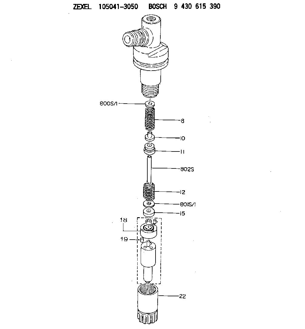
| 8. | [1] | 150562-6500 | COMPRESSION SPRING |
| 10. | [1] | 150560-2001 | SLOTTED WASHER |
| 11. | [1] | 150624-1800 | BUSHING |
| 12. | [1] | 150562-6600 | COMPRESSION SPRING |
| 15. | [1] | 150560-2100 | SLOTTED WASHER |
| 16. | [2] | 150525-1701 | BEARING PIN |
| 19. | [2] | 150508-3300 | BEARING PIN |
| 22. | [1] | 150651-6600 | NOZZLE-RETAINING NUT |
| 800S/1. | [1] | 150539-0700 | SHIM D8.9&3.8T0.40 |
| 800S/1. | [1] | 150539-0800 | SHIM D8.9&3.8T0.50 |
| 800S/1. | [1] | 150539-0900 | SHIM D8.9&3.8T0.52 |
| 800S/1. | [1] | 150539-1000 | SHIM D8.9&3.8T0.54 |
| 800S/1. | [1] | 150539-1100 | SHIM D8.9&3.8T0.56 |
| 800S/1. | [1] | 150539-1200 | SHIM D8.9&3.8T0.58 |
| 800S/1. | [1] | 150539-1300 | SHIM D8.9&3.8T0.60 |
| 800S/1. | [1] | 150539-1400 | SHIM D8.9&3.8T0.70 |
| 801S/1. | [1] | 150590-0600 | SHIM D9.9&4.8T0.40 |
| 801S/1. | [1] | 150590-0700 | SHIM D9.9&4.8T0.50 |
| 801S/1. | [1] | 150590-0800 | SHIM D9.9&4.8T0.52 |
| 801S/1. | [1] | 150590-0900 | SHIM D9.9&4.8T0.54 |
| 801S/1. | [1] | 150590-1000 | SHIM D9.9&4.8T0.56 |
| 801S/1. | [1] | 150590-1100 | SHIM D9.9&4.8T0.58 |
| 801S/1. | [1] | 150590-1200 | SHIM D9.9&4.8T0.60 |
| 801S/1. | [1] | 150590-1300 | SHIM D9.9&4.8T0.70 |
| 802S. | [0] | 150583-0000 | STOP PIN L36.06 |
Cross reference number
Zexel num
Bosch num
Firm num
Name
Information:
1. Remove the fuel ratio control, fuel shutoff solenoid, and idle screw housing from the governor housing (1). 2. Remove screw (2) that holds rack stop collar on.3. Remove rack stop collar (5), collar (3) and spring (4).4. Remove the bolts that hold governor housing to fuel injection pump housing.5. Remove the governor housing. 6. Remove seat assembly (8), governor spring (6) and washer type spring (7).7. Remove three bolts (11) and lock (9) that hold cylinder and weight assembly (10) to fuel injection pump housing.8. Pull the cylinder and weight assembly off the location dowels. 9. Move cylinder and weight assembly to the side to remove piston from rack (12).Connection Of Governor To Fuel Injection Pump Housing
1. Connect cylinder and weight assembly (1) to rack (2). 2. Push cylinder and weight assembly on to location dowels of pump housing and install bolts (3) and lock.3. Install the spring type washer on bolt (4) so the inside diameter of spring will make contact with the guide in governor housing (6). Install governor spring (7), washer type spring (8) and collar (5).4. Put governor housing (6) in place on the pump housing and install the bolts. 5. Install spring (12), collar (11) and rack stop collar (9).6. Install screw (10) in rack stop collar. 7. Install the idle screw housing, shutoff solenoid and fuel ratio control on the governor housing.8. Make an adjustment to the governor. See RACK SETTING AND GOVERNOR ADJUSTMENTS in TESTING AND ADJUSTING.end by:a) install fuel injection pump housing and governorDisassemble Governor
start by:a) separation of governor from fuel injection pump housing 1. Remove seat retaining ring (1) and pin (2). 2. Remove seat (3), bolt (4), washers (5) and spring (6).3. Remove the sleeve and bearing assembly from the cylinder and weight assemblies. 4. Remove retaining ring (7) from sleeve (8).5. Remove bearing (9) and races (10) from sleeve (8). 6. Remove valve (11) from piston (12).7. Remove the retaining ring (13) from the weight assembly (14).8. Remove weight assembly (14).9. Remove piston (12) and sleeve (15) from cylinder (16).10. Remove the O-ring seal from sleeve (15). 11. Remove speed limiter plug (17), spring (18) and plunger (19) from the governor housing.12. Remove high idle screw (21) and low idle screw (20). 13. Remove the bolt (22) and lock from the lever (24).14. Remove shaft (23) and lever (24) from governor housing.15. Remove the seal from the housing.16. Remove two bearings from the housing. Assemble Governor
1. Install detent plunger, spring and pin in levers.2. Install bearings in each side of the governor housing with tooling (A).3. Install levers and shaft in governor housing. The position of the bearings can make a difference in the position of the levers. With the levers pushed against the bearings on the boss side, clearance (X) between the guide for the governor spring and levers must be approximately .135 in. (3.43 mm). With levers pushed against other side the clearance (Y) on the other side must be approximately .100 in. (2.54