Information nozzle-holder
BOSCH
9 430 615 919
9430615919
ZEXEL
105031-4800
1050314800
ISUZU
1153300540
1153300540

Rating:
Scheme ###:
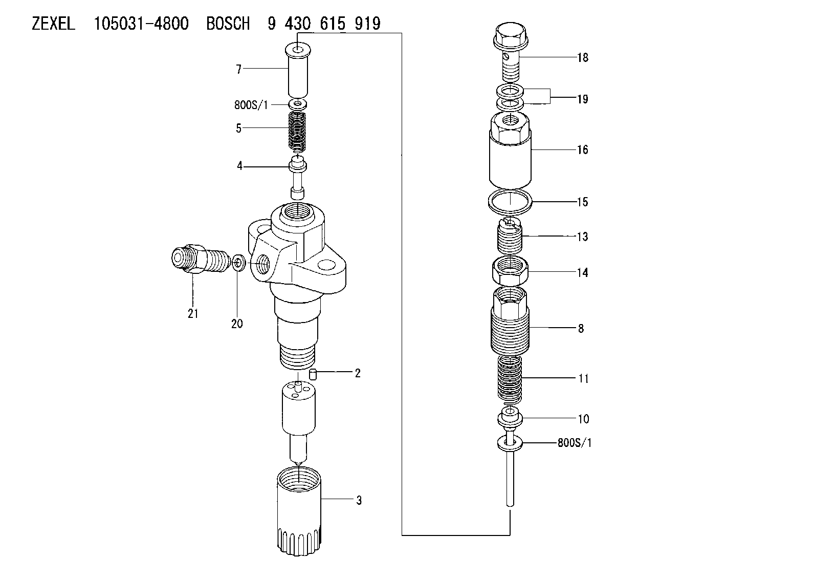
| 2. | [2] | 150508-3300 | BEARING PIN |
| 3. | [1] | 150650-5300 | NOZZLE-RETAINING NUT |
| 4. | [1] | 150550-4800 | STOP PIN |
| 5. | [1] | 150562-4400 | COMPRESSION SPRING |
| 7. | [1] | 150570-0400 | SPACER BUSHING |
| 8. | [1] | 150571-0000 | SET OF NUTS |
| 10. | [1] | 150572-0420 | STOP PIN |
| 11. | [1] | 150562-3100 | COMPRESSION SPRING |
| 13. | [1] | 150565-5500 | THREADED PIN |
| 14. | [1] | 150519-4600 | UNION NUT |
| 15. | [1] | 029332-2030 | GASKET D25.5&22T1 |
| 16. | [1] | 150567-8300 | CAP NUT |
| 18. | [1] | 139808-0000 | EYE BOLT |
| 19. | [2] | 139508-0000 | GASKET D13.2&8.2T1 |
| 20. | [1] | 029300-3100 | GASKET |
| 21. | [1] | 150645-4900 | INLET UNION |
| 800S/1. | [0] | 150523-5000 | SHIM D11.5&4.5T0.50 |
| 800S/1. | [0] | 150523-5100 | SHIM D11.5&4.5T0.52 |
| 800S/1. | [0] | 150523-5200 | SHIM D11.5&4.5T0.54 |
| 800S/1. | [0] | 150523-5300 | SHIM D11.5&4.5T0.56 |
| 800S/1. | [0] | 150523-5400 | SHIM D11.5&4.5T0.58 |
| 800S/1. | [0] | 150523-5500 | SHIM D11.5&4.5T0.60 |
| 800S/1. | [0] | 150523-6000 | SHIM D11.5&4.5T0.70 |
| 800S/1. | [0] | 150523-6500 | SHIM D11.5&4.5T0.80 |
| 800S/1. | [0] | 150523-7000 | SHIM D11.5&4.5T0.90 |
| 800S/1. | [0] | 150523-7500 | SHIM D11.5&4.5T1.00 |
| 800S/1. | [0] | 150523-7500 | SHIM D11.5&4.5T1.00 |
| 800S/1. | [0] | 150532-6700 | SHIM D11.5&4.5T0.1 |
| 800S/1. | [0] | 150532-6800 | SHIM D11.5&4.5T0.2 |
| 800S/1. | [0] | 150532-6900 | SHIM D11.5&4.5T0.3 |
| 800S/1. | [0] | 150532-7000 | SHIM D11.5&4.5T0.4 |
Include in #1:
106671-1470
as NOZZLE-HOLDER
Cross reference number
Zexel num
Bosch num
Firm num
Name
Information:
Illustration 23. (2) 141-6737 Adjustable Microgauge.
(7) Top of the 3P-1542 Barrel. (8) 141-6727 Calibration Pump Assembly.1. Place the 141-6737 Adjustable Microgauge on top of the 3P-1542 Barrel of the 141-6727 Calibration Pump Assembly.2. When starting to torque 124-5932 Lever Assemblies, the difference between the face of the 141-6730 Plunger and the 2N-2658 Bolt is about 0.03 mm (.001 in). By setting the 141-6737 Adjustable Microgauge (2) on top of the 141-6727 Calibration Pump Assembly (8), the 141-6737 Plunger can be positioned 25.40 mm (.001 in) above the face of the 3P-1542 Barrel (7).
Illustration 24. (9) 2N-2658 Bolt. (10) 124-5940 Shutoff Lever.3. As the 2N-2658 Bolt (9) is torqued, the 141-6730 Plunger will move down flush with the 3P-1542 Barrel (7) or will be very close to being flush. The calibration can begin from this point. The 2N-2658 Bolts must freely turn in and out of the 124-5940 Shutoff Levers (10) because the calibration depends on where the head of the 2N-2658 Bolt (9) first begins to clamp the 124-5940 Shutoff Lever for the starting point of the calibration.End Play Adjustment
1. In order to save time, use two torque wrenches (color-coding is convenient for distinguishing between the two wrenches). Set one torque wrench to 1.7 N m (15 lb in) and the second torque wrench to N m (35 lb in).
Illustration 25. (1) 124-5941 Shaft. (2) 4N-1826 Dowel on one end of the HSMFS Injection Pump Group. (3) 126-7232 Dowels.2. Adjust the end play in the 124-5941 Shaft. The SMFS 109-0324 Governor And Fuel Injection Pump Group had the dowel in the middle of the sleeve and a large amount of end play in the shaft was acceptable. Now that the 126-7232 Dowels (3) are between two 124-5934 Sleeves, the amount of end play is important. It is necessary that an adjustment be performed to minimize the amount of end play in the 124-5941 Shaft (1).3. The 126-7232 Dowels (3) are located between two 124-5934 Sleeves. Set the 126-7232 Dowels between 0.25 to 0.40 mm (.010 to .016 in) by tapping in the 4N-1826 Dowels (2) until the desired end play is achieved.* With the 1.7 N m (15 lb in) torque wrench, torque the 2N-2658 Bolts to 1.7 N m (15 lb in).* Then use the 4 N m (35 lb in) torque wrench to torque the 2N-2658 Bolts to 3.4 N m (30 lb in) in order to calibrate within specifications.Calibrating the 124-5932 Lever Assemblies.
Illustration 26. Calibrating the 124-5932 Lever Assemblies.
(1) 2N-2658 Bolts. (2) 124-5940 Shutoff Lever.1. Begin with the first 2N-2658 Bolt (1) and turn it until it just begins to clamp (feels snug) on the 124-5940 Shutoff Lever (2).2. Move to the other side and turn the second 2N-2658 Bolt (1) until just begins to clamp (feels snug).* Alternate between sides and tighten each 2N-2658 Bolt about 15 degrees each time.
Illustration 27. View of the HSMFS Injection Pump Group.
(3) Top of the 141-6730 Plunger shown flush with the 3P-1542 Barrel (4).3. Continue until the torque