Information nozzle-holder assembly
BOSCH
9 430 615 181
9430615181
ZEXEL
105031-3620
1050313620

Rating:
Scheme ###:
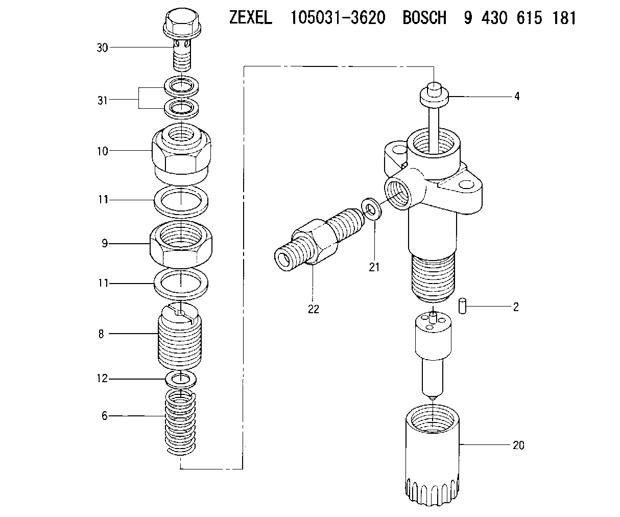
| 2. | [2] | 150508-3300 | BEARING PIN |
| 4. | [1] | 150510-9720 | STOP PIN |
| 6. | [1] | 150516-3100 | COMPRESSION SPRING |
| 8. | [1] | 150518-5600 | THREADED PIN |
| 9. | [1] | 150519-3800 | UNION NUT |
| 10. | [1] | 150567-6300 | CAP NUT |
| 11. | [2] | 029332-2030 | GASKET D25.5&22T1 |
| 11. | [2] | 029332-2030 | GASKET D25.5&22T1 |
| 12. | [1] | 029300-8270 | PLAIN WASHER |
| 20. | [1] | 150637-1800 | NOZZLE-RETAINING NUT |
| 21. | [1] | 150602-1700 | GASKET |
| 22. | [1] | 150645-3800 | INLET UNION |
| 30. | [1] | 139808-0000 | EYE BOLT |
| 31. | [2] | 139508-0000 | GASKET D13.2&8.2T1 |
Include in #1:
101601-7440
as NOZZLE-HOLDER
Cross reference number
Zexel num
Bosch num
Firm num
Name
105031-3620
9 430 615 181
NOZZLE-HOLDER ASSEMBLY
* K 53LZ NH NH
* K 53LZ NH NH
Information:
To many, the diesel principle may not be new, however, the special features of Caterpillar Diesel Truck Engines require that the operator and the maintenance personnel become acquainted with the systems in order to give the engine the best possible care. Maximum engine life depends a great deal on a good maintenance schedule performed by reliable personnel with a basic understanding of the working principles and systems.Diesel Engine Principle
This diesel engine operates on the reciprocating piston 4-stroke cycle, compression ignition principle, and burns fuels commercially known as diesel fuels. The basic differences between the spark ignition engine and the diesel engine are; the method of introducing fuel into the system and the method by which the fuel is ignited.The engine always takes a full charge of air into a cylinder on each inlet stroke, compresses it in an extremely small space causing the air to reach temperatures over 1000°F (537°C.). Fuel is injected into the cylinder as the piston nears the top of the compression stroke, where it mixes with the compressed air, and immediately starts to burn. This is called self-ignition, or spontaneous ignition. The expansion of the burning gases forces the piston down on a power stroke. Four Stroke Cycle Principle
The four stroke cycle engine has separate strokes for each basic function. The four strokes and the order in which they occur are: Intake, compression, power and exhaust.It must be remembered that for the four stroke cycle to function the inlet valves, exhaust valves and fuel injection must be timed in proper sequence with the piston. This is accomplished by timing gears between the crankshaft, the valve train and injection pumps. Intake Stroke: As the piston moves down on the inlet stroke, the inlet valve is opened and exhaust valve is closed by the camshaft and rocker arm arrangement. Air is drawn in through the air cleaner and intake valve by the partial vacuum caused by the piston traveling downward. Compression Stroke: At the end of the intake stroke the inlet valve closes and the exhaust valve remains closed. As the piston moves up, the air is compressed into an extremely small space causing the air temperature to rise high enough to ignite fuel. As the piston reaches near the top of the stroke, a measured amount of fuel is injected into the cylinder where it mixes with the compressed air and ignition begins. The atomized and burning fuel then rushes throughout the cylinder above the piston for complete combustion. Power Stroke: The piston is forced down by the pressure of the expanding and burning gases in the cylinder above the piston. During this power stroke, the intake and exhaust valves are closed. Exhaust Stroke: When the piston reaches the bottom of the power stroke the cylinder is filled with burned gases which must be expelled. As the piston begins its upward travel on the exhaust stroke, the exhaust valve is opened by the exhaust lobe on the cam. As the piston moves up, it forces
Have questions with 105031-3620?
Group cross 105031-3620 ZEXEL
Isuzu
105031-3620
9 430 615 181
NOZZLE-HOLDER ASSEMBLY